
chamfer
Used to remove sharp edges and improve assembly and safety; if there are appearance/grip surface requirements, the chamfer size and edge standards can be specified in the remarks.
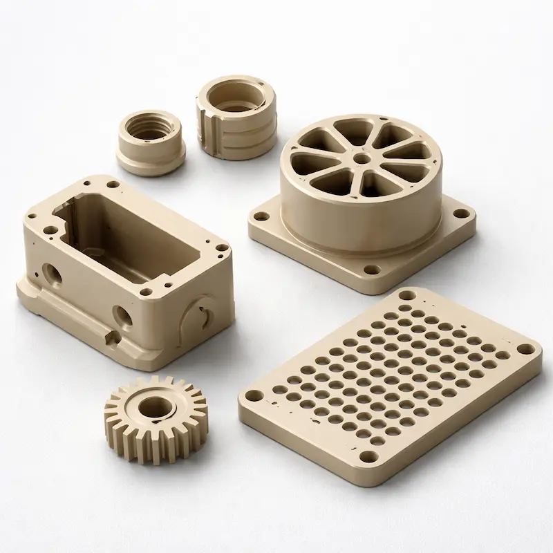
PEEK is a high-performance engineering plastic with excellent heat and chemical resistance, strength, dimensional stability, wear resistance, and fatigue performance for demanding functional parts.
Quote checklist: Upload your 3D model and, when available, a 2D drawing. Identify the required process, material, quantity, critical dimensions, finish, appearance standard, and target delivery date.
Engineering note: Values below are typical reference ranges. Final manufacturability, tolerances, material condition, surface finish, cost, and lead time depend on the drawing, geometry, quantity, and selected process.
Upload CAD files and mark critical features for an engineering review before production.
| Process | CNC Machining |
|---|---|
| Material | PEEK |
| Accuracy | ±0.2 mm |
| Minimum wall thickness | 1.0mm |
| Service temperature | 300-600℃ |
| Tensile strength | 450-1100MPa |
| Density | 7.7-8.5 g/cm³ |
| Applications | Suitable for rapid processing and small batch production of structural parts and end-use parts. If you encounter more specific needs such as corrosion resistance/high strength/wear resistance/high temperature resistance, you can upgrade and select in the corresponding material system. |
| Finishing | Chamfering, grinding, bonding, screen printing, laser engraving |
| Typical lead time | Relevant to size, quantity, structural complexity and finishing; clear delivery and expedited options will be given after uploading the file |
Used to remove sharp edges and improve assembly and safety; if there are appearance/grip surface requirements, the chamfer size and edge standards can be specified in the remarks.
It is used to improve the knife pattern and touch, and improve the consistency of appearance; please mark or note "Appearance surface first" on the appearance side.
Suitable for assembly after component processing; it is recommended to reserve positioning and bonding areas during the structural design stage, and explain the use environment and strength targets.
Suitable for logos, scales and other graphic information; it is recommended to provide vector files (AI/PDF/SVG) and position and size instructions.
Suitable for serial numbers, QR codes, nameplate information, etc.; can achieve a more wear-resistant identification effect. It is recommended to provide content and size/position requirements.
It is suitable for rapid processing and small batch production of structural parts and end-use parts, and is convenient for direct assembly verification or as delivery parts.
When you have more specific goals in terms of temperature resistance, you can describe the working conditions in the inquiry remarks, and we will make an assessment based on the structure and processing route.
Suitable for projects that pay more attention to corrosion resistance, electrical insulation and other requirements; suggestions can be given based on specific media/environments and assembly methods.
Supports information presentation methods such as screen printing and laser engraving; at the same time, the touch feel and edge consistency can be improved through polishing and chamfering.
PEEK is suitable for rapid processing and small batch production of structural parts and end-use parts. It is commonly used in scenarios such as assembly verification, trial production of functional parts, and small batch delivery. If you have clear goals for high temperature resistance, corrosion resistance, electrical insulation or lightweight, it is recommended to describe the usage conditions in the inquiry remarks to facilitate project evaluation.
Key parameters displayed on this page include accuracy, minimum wall thickness, temperature resistance, tensile strength, density, etc. What is more critical to the actual quote is: structural complexity, key tolerances and inspection diameters, thin-walled/deep cavity characteristics, assembly hole accuracy requirements, and whether finishing such as chamfering/grinding/screen printing/radium engraving is required.
For thin-walled parts, it is recommended to focus on: whether the wall thickness is uniform, whether there is a risk of deformation caused by large plane thin walls, deep cavity thin wall combinations, clamping and processing routes. If there are critical thin-walled areas, please mark the critical dimensions and explain the stress/usage conditions in the remarks. We will prioritize the evaluation in DFM.
It is recommended to provide 3D + 2D: 3D (STEP/STP, IGES/IGS) for structure and processing evaluation; 2D (PDF/DWG/DXF) for critical dimensions, tolerances and inspection criteria confirmation. Quotes are also available for 3D only, but critical tolerances are recommended to be stated in remarks.
The machining quote depends not only on the volume, but also on the structure and process: deep cavities/narrow grooves/clear corners, thin-walls and easy deformation, the number of processing surfaces, the number of clampings, key tolerances and inspection requirements, and finishing (chamfering, grinding, screen printing, laser engraving, bonding) will significantly affect the cost and lead time.
Supported finishing includes: chamfering, grinding, bonding, screen printing, and laser engraving. It is recommended to write clearly in the remarks: which kind of finishing is required, the corresponding area/surface, appearance standards or content documents (screen printing/laser engraving) and delivery requirements, so that an accurate quote can be given at one time.
It is recommended to provide 2D annotations and clarify the purpose of the holes (clearance fit/interference fit/locating pin/screw through hole, etc.), tolerance zone and datum. If the consistency of repeated assembly is high, please also note the inspection method and assembly times/stress direction, and we will choose a more stable processing and inspection strategy accordingly.
It is recommended to reserve a positioning structure (steps/positioning pin holes/stops), sufficient bonding area, and try to avoid only end-face connection. When making an inquiry, please indicate the force-bearing method after bonding, the usage environment and whether hidden seams are needed. We will recommend a more appropriate component and bonding solution based on the structure.
Please define the appearance surface/key surface in the drawing or remarks, and we will prioritize the processing surface sequence and tooling strategy; if you need to further improve the touch feel and knife pattern, you can choose polishing and explain the acceptable appearance standards (for example, slight knife marks are allowed/scratches are not allowed, etc.).
It is recommended that you also provide/explain when uploading the file:
You only need three steps: Upload drawings → Confirm project evaluation and quote → Production and delivery after confirmation.