
Sand blasting (improved appearance and feel)
Used to reduce metal printing surface roughness and powder sintering marks to obtain a more uniform matte appearance; more friendly to non-sealed appearance surfaces.
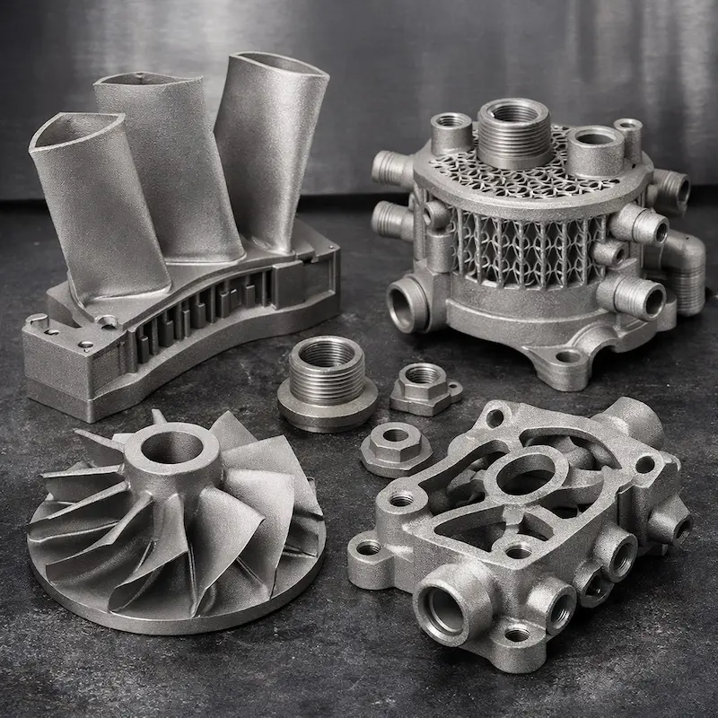
Nickel-Based Superalloy is a metal 3D-printing option for high-temperature parts that require strength, reliability, and complex internal geometry.
Quote checklist: Upload your 3D model and, when available, a 2D drawing. Identify the required process, material, quantity, critical dimensions, finish, appearance standard, and target delivery date.
Engineering note: Values below are typical reference ranges. Final manufacturability, tolerances, material condition, surface finish, cost, and lead time depend on the drawing, geometry, quantity, and selected process.
Upload CAD files and mark critical features for an engineering review before production.
| Process | SLM metal 3D printing (nickel-based superalloys) |
|---|---|
| Material system | Nickel-based high-temperature alloy (high temperature resistance is preferred; suitable for one-piece molding of complex structures) |
| Dimensional tolerance | ±0.20 mm (common reference; it is recommended to mark tolerances and reserve finishing allowance for key mating surfaces) |
| Minimum wall thickness | ≥ 1.0 mm (Thin-walled/long cantilevers are recommended to be reinforced and optimally placed to avoid the risk of deformation and cracking) |
| Minimum aperture | Recommended ≥ 2.0–3.0 mm (deep holes/internal cavities need to be evaluated for cleaning; it is recommended to leave a margin for assembly holes before tapping/reaming) |
| Layer thickness | Commonly used 0.03–0.06 mm (equipment/parameter dependent; thinner layer thickness usually improves detail but increases cost) |
| Service temperature | 650℃ (please note the maximum temperature, duration and medium for high temperature working conditions) |
| Tensile strength | 900–1300 MPa (related to heat treatment status/build direction) |
| Density | 8.2 g/cm³ |
| Surface roughness | The formed surface is relatively rough; sandblasting can improve the appearance and feel, and finishing is recommended for sealing/mating surfaces. |
| Heat treatment/performance criteria | Heat treatment and stress relief can be evaluated according to working conditions; if you need to benchmark the criteria of a standard grade, please specify it in the remarks. |
| Assembly and threading | support Tapping; Please indicate the thread specification (such as M3/M4/M5, etc.), quantity and location. It is recommended to provide 2D annotations and fit requirements for critical assembly holes. |
| Finishing | Sand blasting and tapping |
| Typical lead time | Related to size, quantity, placement, whether heat treatment and finishing are required; clear delivery and expedited options will be given after uploading the file |
Used to reduce metal printing surface roughness and powder sintering marks to obtain a more uniform matte appearance; more friendly to non-sealed appearance surfaces.
Suitable for screw connections and assembly verification. Please provide thread specifications, number of holes and key hole matching requirements in the remarks; under high temperature conditions, it is recommended to clarify the assembly method and force direction.
Facing the hot-end environment and high-temperature functional validation requirements, it is easier to maintain structural performance and reliability at higher temperatures.
Suitable for complex internal flow channels, topology optimization and integrated structures, reducing welding/assembly and shortening iteration cycles.
Through placement optimization, heat treatment and key surface finishing, more controllable assembly accuracy and strength can be achieved.
support Sand blasting + tapping Quickly enter assembly verification; secondary processing strategies can be combined with key hole locations to improve consistency.
Nickel-Based Superalloy is more suitable for metal functional parts and verification parts of "high temperature working conditions + complex structures". Its advantages are concentrated in:
It is necessary to focus on manufacturability and subsequent processing strategies:
It is recommended to refer to the key requirements in your 2D annotations/notes, and also refer to the typical reference values on this page:
We support mainstream project files:
Faster and more accurate approach: priority delivery STEP + 2D annotation(Or write down the key holes/critical surfaces and assembly requirements in the notes).
SLM nickel-based superalloy quotes are usually determined by the following factors:
Commonly used finishing of this material is:
If it is a critical assembly hole, it is recommended to provide 2D markings and reserve a secondary processing strategy (reaming/tapping sequence).
Complex internal flow channels can be made, but "powder can be cleaned/powder can be discharged" needs to be considered in the design:
Common risks in SLM mostly come from thermal stress and weak structures:
The lead time is related to the size, quantity, placement difficulty and finishing of the parts. The following situations usually increase the lead time:
Upload your files to get a more accurate delivery estimate and expedited options.
In order to get a faster and more accurate quote, it is recommended to provide/explain when uploading the file:
The process is usually: Upload drawings → Project evaluation/DFM → Quotation and delivery confirmation → Production delivery.