
Sand blasting (unified matte texture)
Used to remove slight knife lines and obtain a more uniform matte surface; exterior parts are often used as a base treatment before anodizing/powder coating/painting.
Aluminum alloy 5052 (Al-Mg series) is renowned for its "corrosion resistance, good formability, and strong stability," making it suitable for aluminum alloy parts that are more sensitive to appearance and environmental adaptability.
Quote checklist: Upload your 3D model and, when available, a 2D drawing. Identify the required process, material, quantity, critical dimensions, finish, appearance standard, and target delivery date.
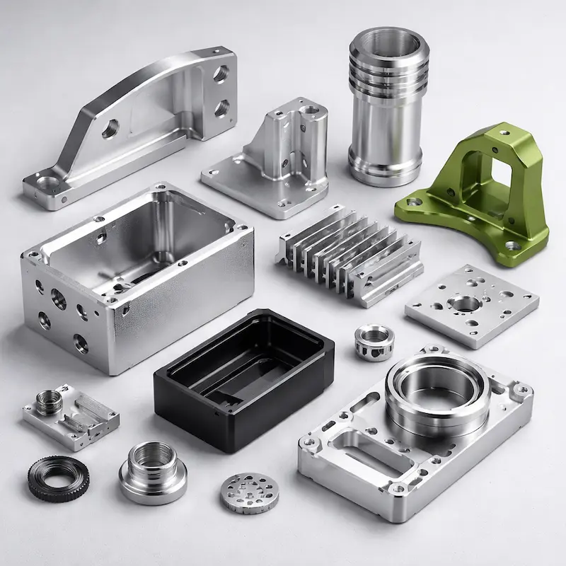
Engineering note: Values below are typical reference ranges. Final manufacturability, tolerances, material condition, surface finish, cost, and lead time depend on the drawing, geometry, quantity, and selected process.
Upload CAD files and mark critical features for an engineering review before production.
| Process | CNC machining (aluminum alloy 5052) |
|---|---|
| Material properties | Corrosion-resistant, good formability, suitable for shell/plate structures and low- to medium-volume processing |
| Machining tolerance | ±0.2 mm (common reference; please mark tolerances and benchmarks for key dimensions) |
| Minimum wall thickness | ≥1.0 mm (common reference; thin-walled/long boards are recommended to undergo DFM review first to control deformation) |
| Service temperature | About 200℃ (engineering reference; actual depends on structure and usage conditions) |
| Tensile strength | 320–460 MPa (reference range; different supply conditions and standards will vary) |
| Density | 2.65 g/cm³ |
| Surface roughness | It is related to the tool path/tool feed/tool and finishing; it is recommended to sandblast/draw the cosmetic parts before anodizing/powder coating/painting to improve consistency. |
| Holes and threads | It is recommended to choose enlarging/reaming for assembly holes/fitting holes according to the purpose; please mark the specifications (M2/M3/M4...) and effective thread depth of the threaded holes. |
| Cosmetic parts suggestions | Please define the display surface and allowable knife pattern/clip printing standards; if screen printing/laser engraving is required, please provide vector files and positioning benchmarks |
| Finishing | Sand blasting, anodizing, powder coating, painting, screen printing, laser engraving, polishing, wire drawing |
| Typical lead time | Related to structural complexity, quantity, inspection requirements and finishing; clear delivery and expedited options will be given after uploading the file |
Used to remove slight knife lines and obtain a more uniform matte surface; exterior parts are often used as a base treatment before anodizing/powder coating/painting.
Improve corrosion resistance and surface hardness, and obtain color and texture; for projects sensitive to color difference, it is recommended to provide color numbers and appearance standards.
The film thickness is higher and the coverage is good, which is suitable for the appearance consistency requirements of the shell parts and batches; the influence of the film thickness on the assembly mating surface needs to be evaluated.
It can achieve richer colors and surface touches (matte/high-gloss, etc.); it is recommended to provide reference pictures and appearance surface definitions.
Suitable for logos, scales, signs and other graphic information; it is recommended to provide vector files and explain the position, size and alignment reference.
Suitable for serial numbers, QR codes and durable markings; for cosmetic parts, it is recommended to clarify the laser engraving position and contrast requirements.
Used to enhance local highlights or a more delicate touch and look; usually required to match appearance standards and inspection samples.
Used for directional texture of cosmetic parts; it is recommended to mark the drawing direction and display surface in the drawings/notes.
It is more advantageous in humid, mild chemical environments or outdoor use scenarios, and is suitable for housing parts and long-term use parts.
It is suitable for plate/shell structures and design routes that are more sensitive to formability, and has a more balanced overall cost and manufacturability.
Sand blasting, anodizing, powder coating, painting, wire drawing, etc. can be combined to facilitate an appearance closer to the finished product.
It is suitable for the iteration rhythm from prototypes to small batches; with clear benchmarks and tolerance markings, the first-time success rate can be significantly improved.
5052 Aluminum Alloy is commonly used in shell parts, covers, brackets and plate structural parts. Its advantages are concentrated in:
Common selection logic can be understood as "different emphasis":
You only need to make a note of "usage environment + load capacity + appearance requirements", and we will be able to give matching suggestions and process routes faster.
It is recommended that you refer to the key requirements marked in the 2D drawings/notes; commonly used reference criterias:
For key features such as mating holes, positioning surfaces, and sealing surfaces, it is recommended to provide a benchmark system and inspection criteria, and confirm them in place once during the quote stage.
We support mainstream 3D/2D project files:
Faster and more accurate approach: priority delivery STEP + 2D annotation, and name the key dimensions/coordination relationships and appearance requirements in the remarks.
The quote of CNC aluminum parts does not only depend on the volume. Common influencing factors include:
The finishing of aluminum alloy 5052 (CNC machining) is subject to materials data; common appearance appeals are usually achieved through the following combinations:
Suggested remarks: Reference image/target texture + display surface definition + color number/grain direction + acceptable mark standards.
Common sources of marks on cosmetic parts include tool path texture, clamping contact marks and edge burrs. For a cleaner look, common practices:
The biggest impact on assembly reliability is usually the hole and reference diameter. It is recommended that you:
Thin-walled and large-planar structures are more susceptible to slight deformation due to clamping, tooling and residual stress. Tips to reduce risk:
In order to get a faster and more accurate quote, it is recommended that you provide/explain when uploading the file:
The process is usually: Upload drawings → Project evaluation/DFM → Quotation and delivery confirmation → Production delivery.