
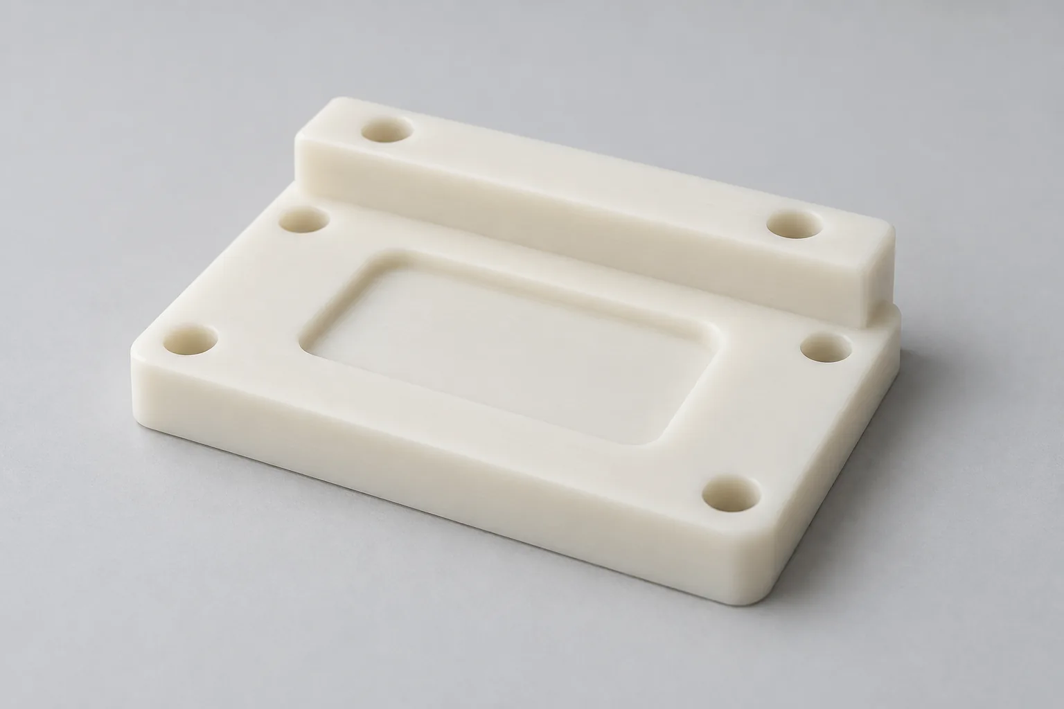
Project overview
Medical imaging equipment
Medical imaging positioning bracket
Prototype-to-low-volume planning; the actual project stage must come from real project data
A medical imaging equipment positioning bracket made from POM by CNC machining, with datum stability and hole-pattern relationships as the central problem
What this case documents—and what it does not
Public evidence
No real project facts were supplied; the sector, component, POM material family, CNC process, and challenge are planning anchors
Confirm from customer files
Geometry, exact grade, moisture or conditioning requirements, datum scheme, hole tolerances, quantity, finish, inspection plan, and result must be verified from authorized files
Present planning anchors as editorial premises, customer-file facts as pending verification, and sensitive or unsupported details as prohibited
Engineering focus
Low-force workholding—explain how support and clamp placement can reduce elastic deformation during machining
Datum and hole-pattern sequencing—show why reference creation and setup transfer affect assembly alignment
Polymer edge and thermal management—describe how tool condition, heat, and chip evacuation can affect burrs and feature stability
The bracket's function and the production question
A positioning bracket can locate a sensor, cover or internal subassembly within medical imaging equipment. Its useful accuracy is the relationship between the mounting surface, locating features and holes, rather than the appearance of an isolated feature.
The proposed route is CNC milling and drilling of POM. It supports planning around drawing-defined interfaces, but the material family alone cannot establish suitability for the application. The exact grade and environment still matter.
- Application: an internal positioning interface, without an identified customer or device model.
- Manufacturing direction: machining a polymer bracket while preserving its assembly references.
- Transition: evaluate how a prototype route could become repeatable low-volume work; the actual project stage is unknown.
- Acceptance: use authorized interface requirements instead of assuming that a successful trial establishes production readiness.
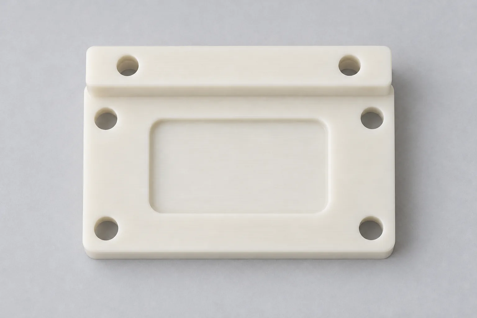
Evidence boundary and information still needed
No real project facts or inspection records have been supplied. The sector, component, material family and proposed processes define the subject to investigate; they do not document a completed case.
| Planning input | Status before a manufacturing commitment |
|---|---|
| POM material | Confirm resin grade, color and any conditioning requirement. |
| Part definition | Obtain controlled geometry, datum scheme and assembly interfaces. |
| Acceptance criteria | Supply tolerances, surface requirements and inspection expectations. |
| Commercial scope | Provide quantity, finish and delivery needs for a grounded quotation. |
Engineering focus: support the part without bending it
A clamp can push a compliant polymer face out of shape. If machining takes place in that deflected position, releasing the clamp can change the face-to-hole relationship. Support beneath the loaded region can reduce that bending, provided the actual geometry allows it.
Favor broad, stable support and clamp positions near supported areas when an exposed span is vulnerable. Where tool access prevents that arrangement, reconsider the setup or support concept before simply tightening the clamp.
- Compare the relevant surface before clamping, while held and after release using a suitable low-force method. If the change follows clamping, revise support and restraint before assigning the error to the cutting path.
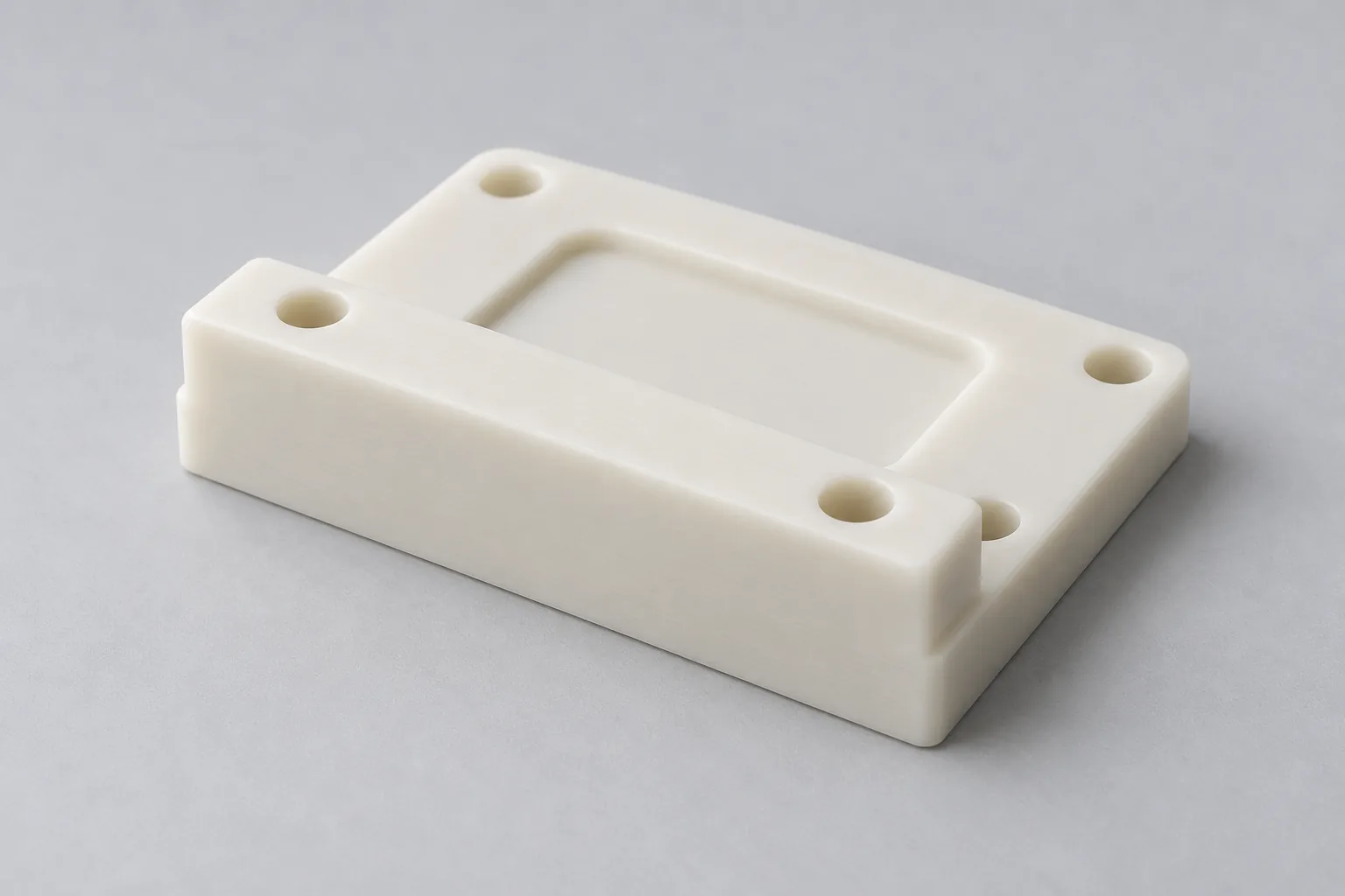
Engineering focus: carry the datum into the hole pattern
A datum is the reference used to locate a feature. Holes machined accurately from different, inconsistent references can still fail to match their assembly interfaces. Chips on a seating face or a changed locating contact can shift the next setup.
Where access permits, create the reference face and related locating features before machining holes from those references. If a transfer is necessary, locate from the drawing's functional scheme and inspect the receiving contacts for debris or damage.
- Measure hole relationships from the intended assembly references after unclamping. A repeatable transfer shift calls for a locating correction; scatter between parts calls for investigation of seating, restraint and material condition.
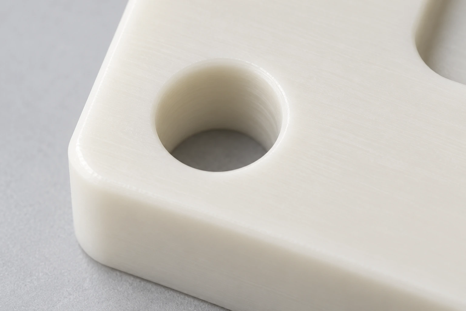
Engineering focus: manage cutting heat and edges
Cutting adds heat, and polymer dimensions can change with temperature. A warm feature may therefore give a different reading after cooling. Worn tools or poor chip clearance can also leave burrs that obstruct seating or disguise an edge.
Choose tooling, chip evacuation and cutting conditions for the confirmed POM grade and geometry. Compare measurements under agreed temperature and handling conditions. Apply deburring without rounding a functional edge; additional stabilization belongs in the route only when specified.
A connected machining route
Keep the references visible through planning, cutting and inspection. Adapt this sequence to the actual shape rather than treating it as a validated recipe.
- Review CAD and the controlled drawing together; resolve conflicting interface and datum definitions.
- Confirm stock identity, grade and required conditioning before deciding how to hold it.
- Plan low-force workholding with support that remains effective where material will be removed.
- Create the reference face and locating features, then check their suitability for subsequent seating.
- Sequence holes and profiles to preserve the functional reference; verify any necessary setup transfer.
- Deburr, stabilize if the specification requires it, and inspect the released part against the agreed criteria.
Verify relationships, not isolated dimensions
Select measurement methods for the feature, access and permitted uncertainty. Contact force itself can influence a compliant part. Candidate methods need assessment against the actual drawing; none is evidence of acceptance until records exist.
| Feature | Control intent | Typical verification to assess |
|---|---|---|
| Mounting face | Stable assembly seating | Appropriate surface measurement or a controlled assembly check. |
| Locating features | Consistent reference contact | Suitable gauges or coordinate measurement without distorting the part. |
| Hole pattern | Position relative to functional datums | CMM or optical measurement with the correct reference alignment. |
| Profile | Clearance and mating fit | Optical inspection or a representative interface check. |
| Threads or inserts, if present | Retention and mating function | Specified gauge and installation checks for the defined interface. |
| Edge condition | Clear seating and clean handling | Visual examination focused on burrs and functional edges. |
Process planning
- Use 6 connected steps: CAD and drawing review
- material and conditioning confirmation
- low-force fixture planning
- reference-face and locating-feature creation
- sequenced hole-pattern and profile machining
- deburring, stabilization if specified, and final verification. Keep all tactics conditional on actual geometry
Quality control
| Feature / control / verification |
|---|
| Use Feature | Control Intent | Typical Verification for mounting face, locating features, hole pattern, profile, threads or inserts if present, and edge condition. Describe gauges, CMM, optical measurement, and assembly checks as candidate methods only |
Prepare your RFQ
3D CAD, controlled 2D drawing, POM grade and color, quantity, tolerances, inserts, finish, assembly interfaces, cleanliness requirements, inspection plan, application environment, and target lead time
Documented outcome and verification boundary
The final case must identify which results are supported by drawings and inspection evidence; no tolerance achievement, repeatability, or device performance is currently established
Do not claim medical certification, guaranteed dimensional stability, perfect hole alignment, production readiness, fixed price, or validated device performance
Prepare the RFQ and define the outcome
Configure a quote by supplying the records below, or upload drawings for an initial manufacturability discussion. Those inputs allow the machining route, inspection scope and delivery assumptions to be compared on the same basis.
The present outcome is a bounded manufacturing plan. A later case can report achieved tolerances and repeatability only where authorized drawings and inspection evidence support them; device-level claims need their own evidence.
- Controlled CAD and drawing, including datums, hole requirements and mating interfaces.
- Material specification with color, conditioning and the intended application environment.
- Requested quantity, target lead time and any relevant supply constraints.
- Defined inserts, finish, edge treatment and cleanliness requirements.
- Inspection plan and available prototype observations, including measurement conditions.
Frequently asked questions
Does a bracket that fits during a prototype trial justify ordering a batch?
Fit is useful evidence for that trial, but it may hide variation in stock, seating or setup transfer. Before expanding the order, agree how repeated parts will be sampled and compared against the controlled interface requirements.
Should a warm part be rejected immediately when its hole positions appear wrong?
Record its handling and temperature condition first, then repeat the check under the agreed inspection conditions. A changed reading can guide the investigation, but it does not excuse a part that fails the specified acceptance test.
Can post-machining deburring solve an alignment problem?
It can remove an obstruction when a burr prevents seating. If the released geometry remains misplaced on clean contacts, further edge work will not restore the required reference relationship.
What extra evidence is needed if the bracket includes an insert?
Supply the insert definition and installation requirements, then check whether installation alters the surrounding geometry or mating function. Passing the bare polymer check does not establish acceptance after that operation.