
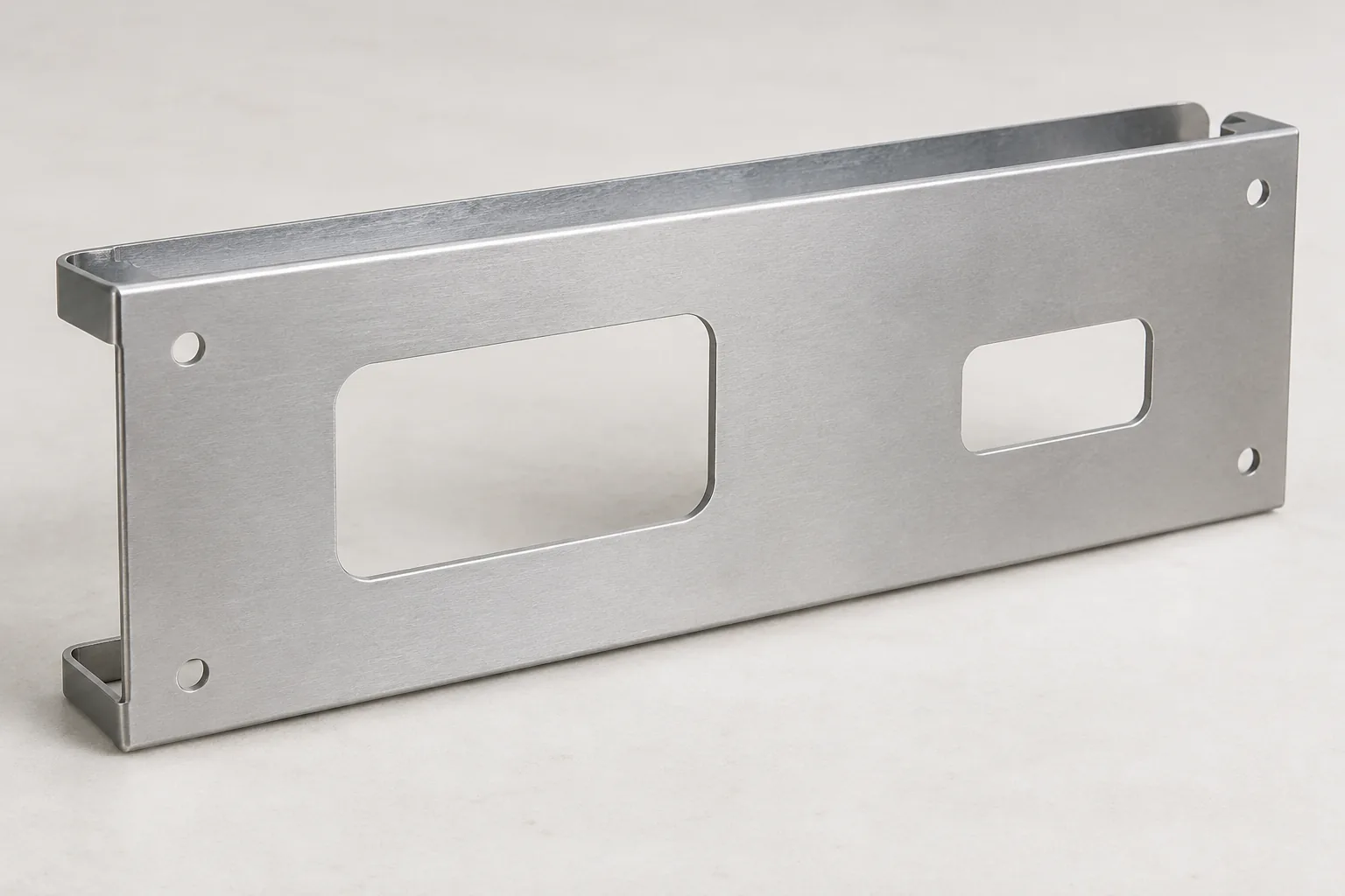
Project overview
EV battery validation and test equipment
Formed sensor and connector panel
Low-volume equipment-build planning; actual stage to be supplied from real project data
Sheet metal fabrication of a 5052 aluminum sensor panel for an EV battery test fixture, centered on interactions among bend geometry, openings, mounting holes, and anodized finish
What this case documents—and what it does not
Public evidence
No executed project evidence was supplied; the application, component, 5052 material, sheet-metal process, and challenge are editorial premises
Confirm from customer files
Flat pattern, thickness, bend radii, tolerances, hardware, cosmetic zones, anodized specification, quantity, inspection criteria, and result must come from approved files
Clearly label editorial anchors, file-confirmed facts, and prohibited inference; the EV application does not identify a customer
Engineering focus
Hole-to-bend interaction—explain how cutout placement, reliefs, and forming deformation influence usable interface locations
Datum strategy across flat and formed states—show why measurement references must match assembly intent
Finish and hardware sequencing—explain how anodizing, masking, countersinks, and inserted hardware can constrain process order
Fixture context and evidence boundary
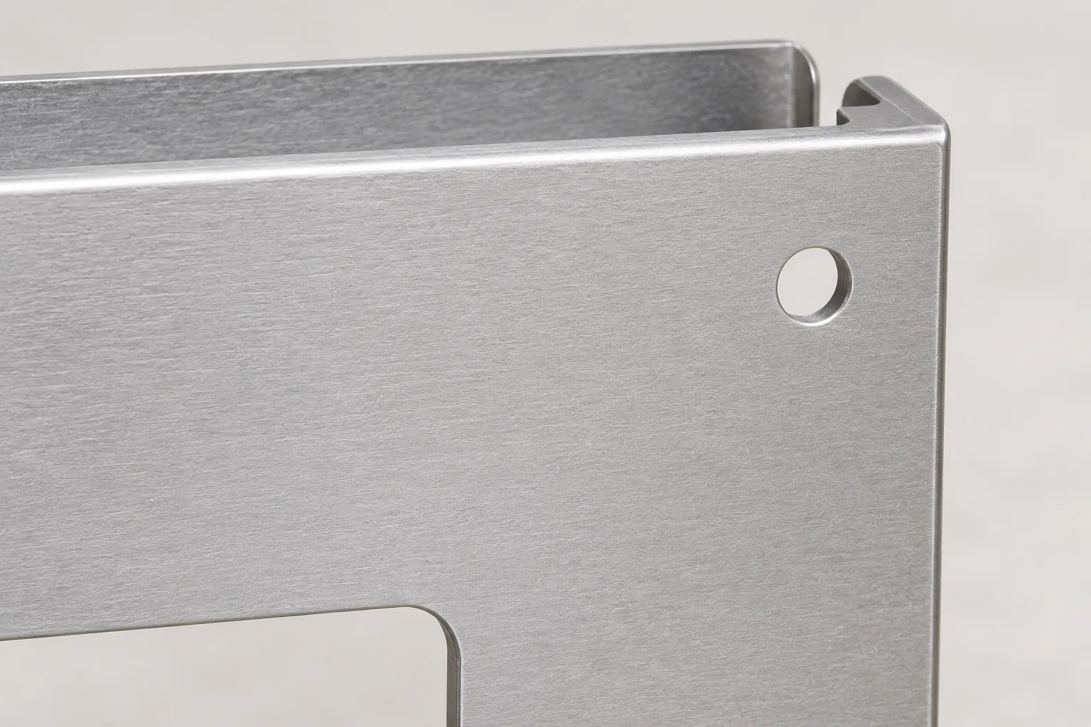
The panel positions sensor, connector and cable interfaces on an EV battery test fixture. Formed flanges provide mounting surfaces, while cutting creates the openings. The 5052 alloy is a planning premise; temper, thickness and bend radius govern whether the proposed geometry is practical.
Manufacturing parameters remain drawing-led: laser cutting and press-brake forming are the proposed route; tolerance, roughness, hardware, finish and quantity await approved files.
- Sector: battery validation and test equipment.
- Component: formed sensor and connector panel.
- Stage: low-volume equipment planning; actual project status requires evidence.
- Application: locate interfaces relative to fixture mounting features.
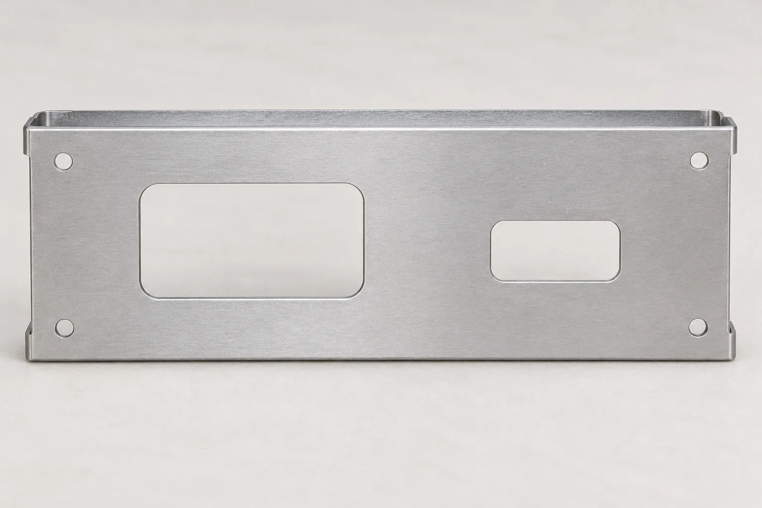
Engineering focus: openings near the bend
A nearby opening can enter the area stretched and compressed during bending. Its edge may change shape or position relative to the flange, leaving a connector difficult to seat even when the original flat cut was correct.
Bend development means working out the flat shape that will become the required formed part. It must place each opening relative to where the flange and mounting references will end up after forming. An opening can keep its shape yet miss the intended assembly location if that flat-to-formed relationship is wrong. Check the developed layout against the formed drawing separately from inspecting local opening distortion.
Inspect the opening's relationship to the bend zone and reliefs. If forming threatens its usable profile, review relocation, relief geometry or a drawing-approved later operation. Where assembly fixes the opening position, verify the proposed tooling and sequence on a representative sample rather than assuming cutting accuracy survives the bend.
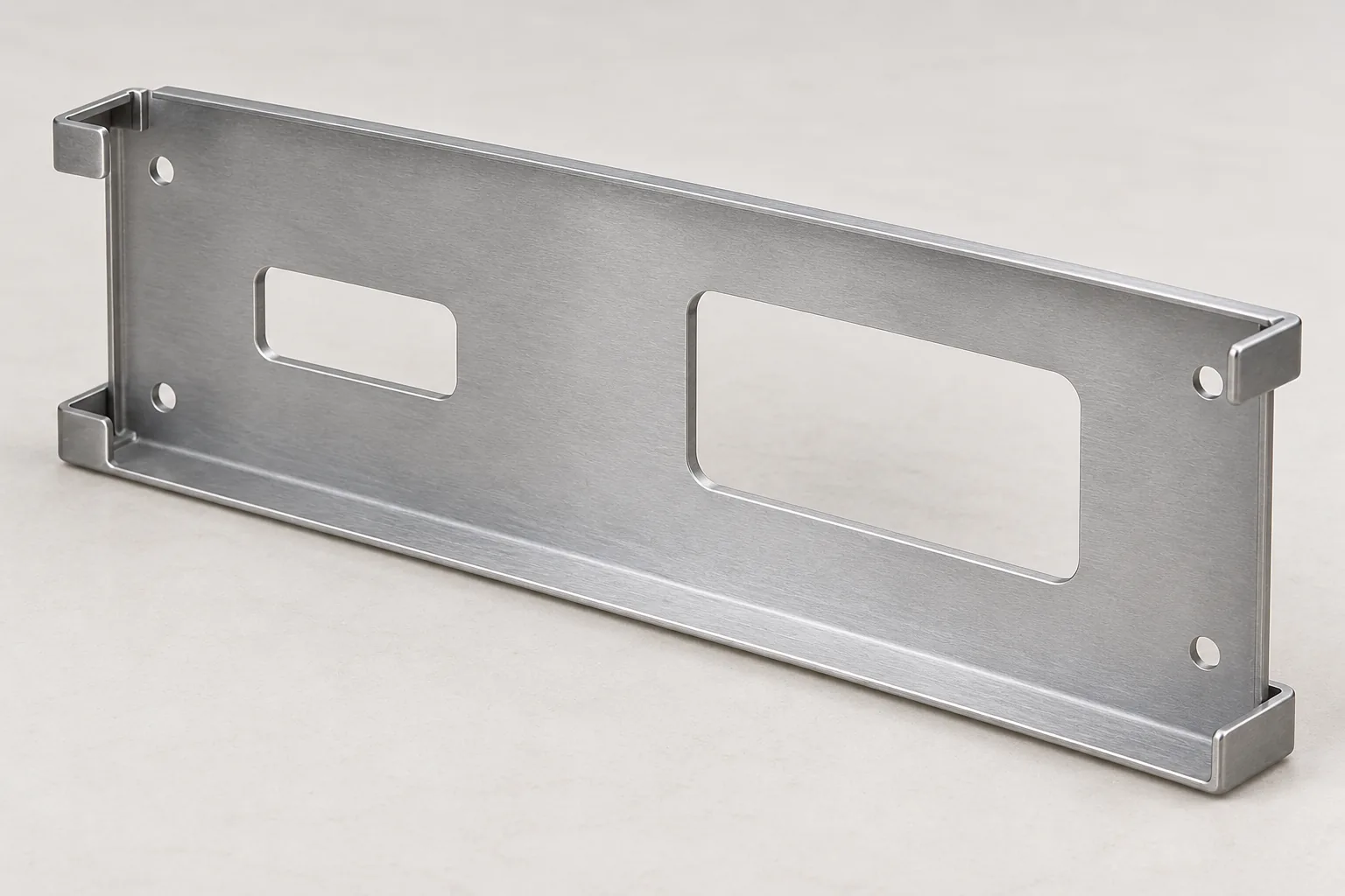
Engineering focus: references that follow assembly
An accurate flat pattern can still produce a misaligned interface if the formed panel is measured from an edge the fixture never uses. A datum is the surface or feature from which a measurement starts; select it to reflect how the panel seats.
Locate the formed part from its intended mounting references, then assess flange angle and opening position together. If those checks pass but the connector binds, examine mating geometry and the assembly tolerance stack before changing the panel.
Engineering focus: anodizing and hardware order
Anodizing creates an oxide surface layer that can affect close-fitting features and electrical contact. Agree masking and cosmetic zones before finishing. A visually even surface alone cannot establish a functional connection.
Where a specified anodized surface must remain intact, plan cuts or countersinks that would remove it before anodizing. Later machining needs an approved requirement for the exposed contact surface or masking arrangement; otherwise it can undermine the required finish at that interface.
Installing hardware before treatment is an option only when the hardware is compatible with the process and required masking can be maintained. Installation afterward avoids exposing incompatible hardware to treatment, but insertion must not damage a required coated seating surface. Use the approved surface, contact and hardware specifications to choose the branch. If neither route protects the interface, resolve masking or installation protection before proceeding.
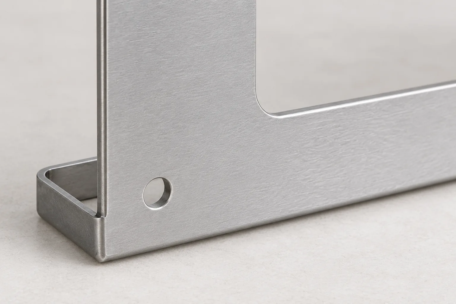
A connected manufacturing plan
Use the following proposed sequence to carry assembly requirements through each handoff. It describes planning actions, not operations already completed.
- Review drawings and mating components to identify functional interfaces.
- Develop the blank and reliefs for the proposed bends, checking that opening locations translate to the required flange and assembly references.
- Laser-cut the agreed flat pattern, retaining its reference features.
- Deburr and prepare edges without changing functional profiles.
- Form in stages that preserve access and protect existing bends.
- Finish and fit hardware along the selected conditional route: complete surface-removing work beforehand unless expressly approved otherwise, and confirm treatment compatibility or protected post-finish installation.
- Verify dimensions, finish and fit against the acceptance criteria.
Quality checks linked to function
Use a common assembly reference when checking the finished panel. If a feature misses its requirement, trace the change back to cutting, forming or finishing, adjust the relevant operation and repeat the affected checks.
| Feature | Control intent | Typical verification |
|---|---|---|
| Flange angles | Seat mounting faces correctly | Check formed angles against the drawing |
| Mounting datums | Reproduce fixture location | Support on intended mating references |
| Hole and connector patterns | Maintain usable interfaces | Inspect positions and trial-fit approved mating parts |
| Edge condition | Protect handling and cables | Inspect burrs and opening edges |
| Finish zones | Preserve specified surfaces | Compare coating and masking with approved requirements |
| Installed hardware | Maintain seating and engagement | Check installation and mating engagement |
Process planning
- Present 7 steps: drawing and assembly review
- bend-development and relief review
- flat-pattern cutting
- deburring and edge preparation
- staged press-brake forming
- anodizing and hardware installation in the drawing-approved order
- dimensional, finish, and fit verification. Explain the handoff between steps without asserting they occurred
Quality control
| Feature / control / verification |
|---|
| Use Feature | Control Intent | Typical Verification for flange angles, mounting datums, hole and connector patterns, edge condition, finish zones, and installed hardware |
Prepare your RFQ
3D model, dimensioned flat and formed drawings, alloy and temper, sheet thickness, bend radii, tolerances, cosmetic surfaces, anodized requirements, masking, hardware schedule, quantity, mating components, and target lead time
Documented outcome and verification boundary
Publish only customer-approved dimensions, inspection evidence, and finish results; no current evidence proves assembly fit, finish consistency, or production repeatability
Do not claim perfect bends, exact fit, flawless anodizing, zero rework, fixed pricing, or guaranteed delivery
Prepare an RFQ that can resolve the route
Supply the model, flat and formed drawings, alloy and temper, sheet thickness, bend radii, tolerances, cosmetic surfaces, anodizing and masking requirements, hardware schedule, quantity, mating components and target lead time.
Include fit observations or inspection records if available. These inputs support a fabrication quote and a decision about bend feasibility, operation order and verification scope. Publish an outcome only after customer-approved dimensional, finish and assembly evidence exists; the present premise supports no guarantee of delivery or acceptance.
Frequently asked questions
What can establish the layout before a flat pattern is approved?
Show how the panel is supported and which connector or sensor must align with its mating part. Mark clearance-only openings separately from locating features so the fabricator can develop the blank around the assembly's functional priorities.
What should a trial sample represent?
Use the intended material condition, forming route and finishing sequence. An unfinished sample can reveal geometry problems but leaves coated-interface behavior unresolved.
How should conflicting hardware and surface requirements be resolved?
Identify whether the joint needs electrical contact, a protected cosmetic face or an uncoated bearing surface, and show where installation force is applied. Ask the designer to prioritize incompatible requirements so masking, hardware choice or assembly access can be revised before quoting the route.