
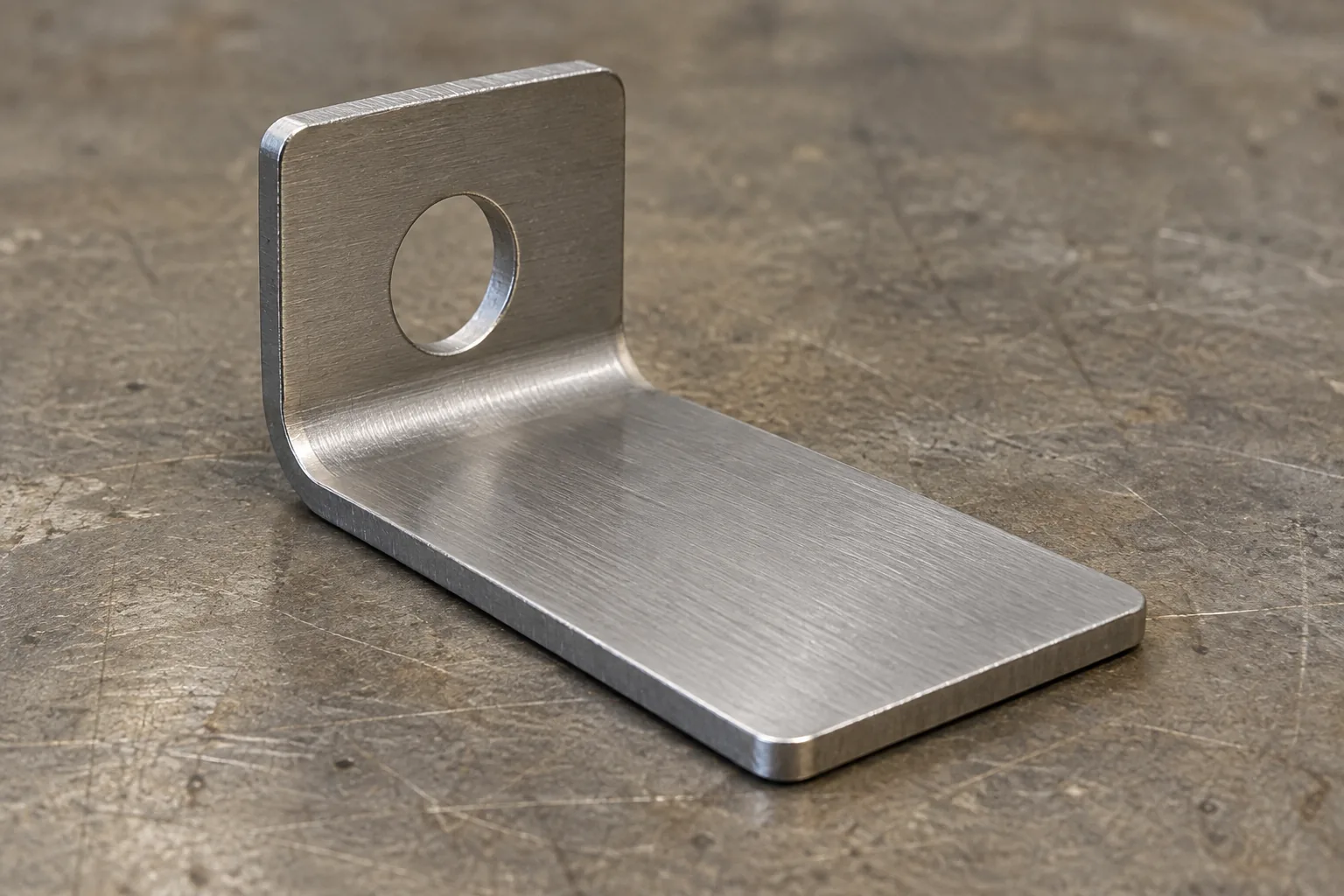
Why a hole close to the bend can lose its shape
Consider a bracket carrying one mounting hole on a short flange. Packaging puts that hole close to the rounded corner, but the mating component needs the fastener at a specific location. This is an illustrative design situation, not a reported production case.
During bending, metal on the outside of the corner stretches while metal on the inside compresses. The metal between them changes curvature. If a hole edge enters this locally deforming region, different parts of its rim can move by different amounts. A round opening may become elongated, and a slot may widen or skew. With enough local strain, the remaining metal between the opening and the bend may tear.
The effect depends on how the part is formed. Sheet thickness, inside bend radius, alloy and temper, grain direction relative to the bend, and the tooling all influence the local response. Hole size and orientation determine how much of the opening encounters that response. A bend line drawn on a flat layout is therefore not a sharp boundary beyond which every feature remains unchanged.
On the first formed sample, inspect the rim under angled light and compare its outline with the intended opening. Look for elongation, a pulled edge, or a crack in the narrow strip beside the bend. These observations identify a problem to investigate; they do not by themselves establish which material or tooling variable caused it.
Why an intact hole can still cause assembly trouble
A hole can remain round and still miss its mating feature. As the flange rotates into position, its bend angle and corner geometry determine where the opening ends up relative to the bracket's base. Variation in the formed angle, including springback after the tooling releases the part, can alter that relationship.
This becomes especially restrictive when the bracket meets a rigid mating part. A fastener must pass through the opening along its intended direction, and the formed corner must leave room for its head, washer, and installation tool. An opening that accepts the screw by itself may still be awkward to use beside the bend.
Locate the formed bracket against the surfaces used in the assembly, then check the hole's position and the fastener's insertion path. If the rim is distorted, examine the local forming response. If the rim is sound but the hole misses its mate, examine the bend geometry and the chosen positional datum. Both effects may occur together.
A larger opening can accommodate some positional variation only where the joint permits extra clearance. It also removes more metal near the corner and may change washer support or locating function. Forcing a screw through a misaligned bracket is not a useful acceptance test.
Choose the change that protects the required interface
Start with the hole's job: does it locate the assembly, carry a fastener with clearance, or provide adjustment? That distinction determines whether shape, position, or access is the controlling requirement. Compare alternatives against that requirement rather than choosing the smallest change to the flat drawing.
Moving the opening farther onto the flat flange is a direct way to reduce its involvement in local bend deformation. Where the mating position cannot move, a longer flange or a changed bend location may create separation while preserving the interface. Both choices consume packaging space.
A relief is a deliberate cutout that gives selected material room to deform. A supplier may propose one where the remaining strip beside the opening would otherwise be pulled during bending. Its suitability depends on the load path, residual edge geometry, finish, and how the cutout joins the bend. It cannot be assumed to preserve the hole's formed position.
| Option | Conditions that favor it | Tradeoff and next decision |
|---|---|---|
| Relocate the hole | The mating interface can move and the flange has usable flat area. | Uses flange space. Check the revised fastener position and available access before changing the drawing. |
| Redesign the flange or bend location | The mating position must stay fixed, but the surrounding envelope can change. | Changes part size or adjacent clearances. Check the assembled envelope and structural function. |
| Add a justified relief | Local material beside the feature needs room to deform and a cutout is acceptable. | Changes the edge and remaining load path. Trial the proposed geometry with the intended bend tooling. |
| Produce the hole after forming | Position relative to formed assembly surfaces is critical and the cutting tool can reach. | Adds setup and handling. Establish the fixture datum, support the flange, and check both sides for deburring access. |
When post-forming holes are worth the extra operation
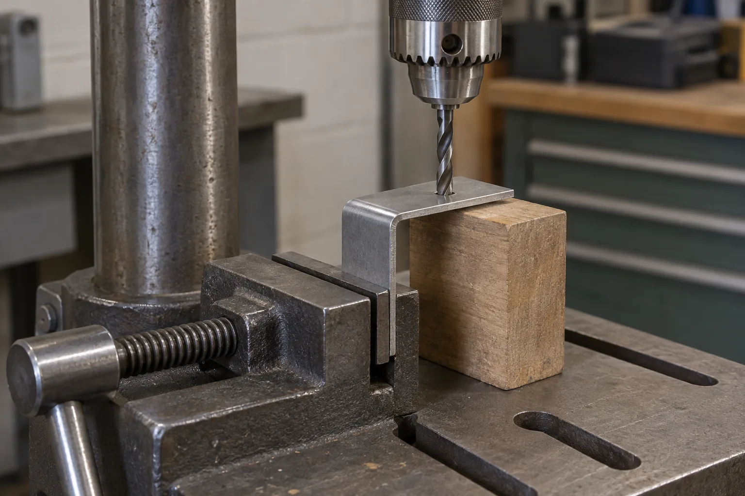
Producing the hole after bending avoids asking a finished opening to pass through the bend operation. It can also locate the hole from the already formed surfaces, which is useful when those surfaces establish the assembly relationship.
The advantage depends on the setup. A flexible flange may move under cutting forces unless it is supported, and an inaccessible underside can make burr removal difficult. The tool, spindle, fixture, and nearby walls all need clearance. A post-forming operation does not correct an unacceptable bend angle or a bracket that sits incorrectly in the assembly.
Ask the supplier to identify the locating surfaces and show how the flange will be held without bending it out of position. If the feature is reachable and can be located from the required datum, compare the extra operation with the space consumed by redesign. If access is blocked, return to flange geometry or the mating arrangement rather than assuming drilling will solve the problem.
Put the functional requirements into the drawing review
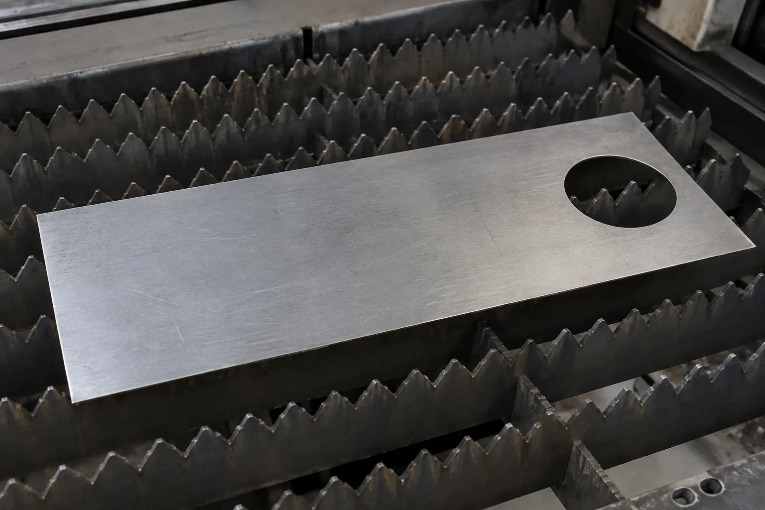
Review the formed drawing and flat layout together. The formed view establishes what must fit; the flat layout describes the starting geometry. A precise laser-cut opening in the flat blank does not establish its final shape or position.
Use the following checks to decide what the drawing and supplier review must resolve. If a controlling input is missing, keep the proposed placement provisional and obtain that input before relying on the design.
- State the hole's actual function: locating, fastener clearance, or adjustment. Include the mating fastener and any washer contact needed by the joint.
- Define the positional datum on the formed part. Identify the assembly seating surfaces and the direction from which the fastener enters.
- Specify the sheet alloy, temper or condition, and thickness. Discuss grain direction where it affects the intended bend and feature placement.
- Define the bend angle and inside radius, including their permitted variation. Show the opening's size, orientation, and relationship to the formed corner.
- Agree the forming method, tooling assumptions, and operation sequence. Include cutting access and deburring when a post-forming hole is proposed.
- Provide the positional tolerance, relevant finish requirements, and planned quantity. Decide whether a supplier forming trial is needed to demonstrate the required fit.
Use a forming trial to choose the next step
When the opening lies near the corner and supplier capability is uncertain, use samples that represent the proposed stock and forming process. Record the rim profile and where the feature sits relative to the surfaces that locate the assembly. Try the intended hardware in place and note where insertion becomes obstructed. Use these records to distinguish a change in the opening itself from positional mismatch or limited installation access.
Separate the observations. If the opening distorts but its center remains acceptable, relocation or a supported relief proposal may address the local strain. If the opening retains its shape but its center varies, examine bend control and datum selection; a properly fixtured post-forming hole may be worth evaluating. If fit is correct but the fastener cannot be installed, change the access geometry.
Prepare the formed drawing, flat layout, material specification, mating-part geometry, hardware details, required tolerances, and any sample observations for your supplier. With these inputs, you can decide whether to move the feature, revise the flange, trial a relief, or price a post-forming operation. Keep final placement and positional capability tied to that specific drawing and process.
Frequently asked questions
Why might one prototype fit while a later batch is difficult to assemble?
One successful fit demonstrates that sample, not the available process variation. Changes in material condition, actual thickness, tooling setup, or formed angle can alter the hole-to-interface relationship. Record those inputs during the trial and evaluate repeated parts against the same assembly datum before treating the fit as repeatable.
Does turning a slot away from the bend solve the problem?
Slot orientation changes which parts of its perimeter encounter local strain, but it also changes the direction in which the joint can adjust. A slot may accommodate mismatch in one direction while leaving the other constrained. Choose orientation from the required adjustment and remaining metal, then verify the formed slot; rotation alone is not a distortion remedy.
Can a supplier's hole-to-bend guideline be used as an acceptance rule?
Use it as a starting layout screen within the material, bend, and tooling conditions for which it was developed. Acceptance still needs the formed feature's allowed shape, positional tolerance, and mating fit. Ask the supplier whether the guideline covers your feature geometry and process before applying it.
What should be checked if the bare bracket fits but the finished part does not?
Check whether the specified finish affects the available opening clearance or seating contact, while also comparing the formed dimensions. Evaluate the joint in its intended finished condition. Enlarging the blank opening without separating finish effects from forming variation can conceal the problem and weaken the intended locating function.