
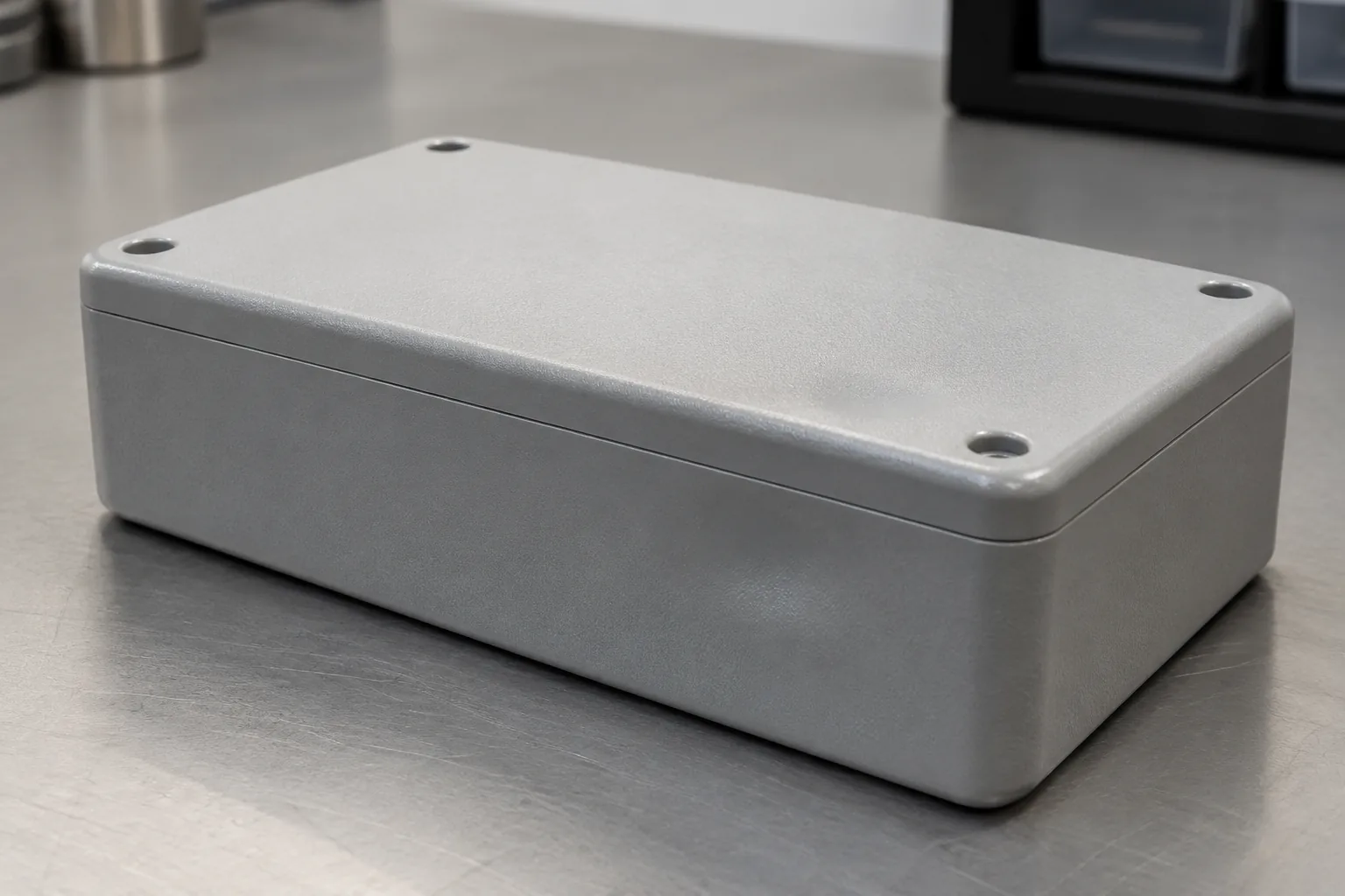
Find the hidden bulk behind the housing surface
A housing can look evenly walled from the outside while its screw bosses and reinforced mounting pads create thick pockets inside. At the point where a boss meets the shell, material can accumulate through the combined geometry of the boss base, connecting rib and outer wall. A cosmetic surface opposite that junction deserves closer attention even when the visible design looks simple.
To assess an injection molding wall thickness transition in CAD, cut through each attachment feature and trace the material from the outer skin to the boss or pad. Compare the local section with the adjacent nominal wall, meaning the intended main shell thickness. Look for solid bases, crowded rib junctions and material that serves no clear load or assembly function. Keep the locations tied to the outside surfaces and mating features that matter to the customer.
Why uneven sections can leave sink or change the fit
Plastic in a locally thick region generally loses heat more slowly than plastic in a nearby thin wall. The outside can become firm while material deeper in the thick region remains hot and continues to shrink. Packing, the pressure used to feed additional material as the part cools, may not compensate fully at that location. The surface can then pull inward and leave a sink mark.
Warpage is a broader shape change. If connected regions shrink differently, or are restrained differently as they cool, the enclosure can bend or twist rather than retain its intended shape. A long edge may lift, a lid may rock or mounting features may stop lining up. These symptoms suggest places to investigate; they do not establish the cause of a particular part.
A thick pocket can also keep the part in the mold longer while it becomes stable enough to remove. When cosmetic rejection or poor fit prompts tool changes, a local design detail can affect both cycle time and development effort. Check whether observed depressions align with heavy sections, then review that pattern alongside gate position, cooling layout, resin shrinkage and processing conditions. If the pattern does not follow the geometry, broaden the investigation before removing material.
Choose the revision that matches the feature's job
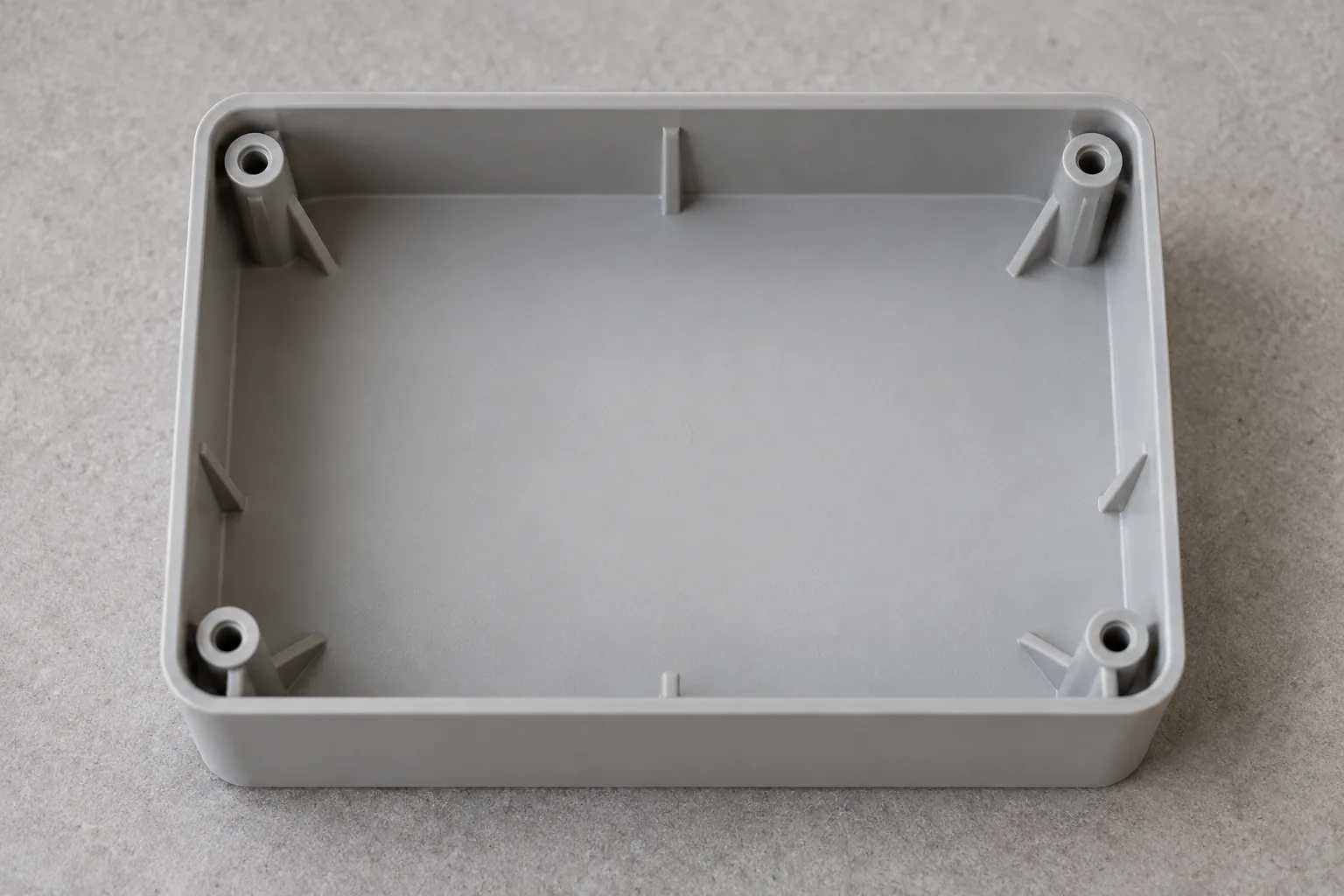
For an oversized boss base or solid mounting pad, coring removes bulk without automatically discarding the attachment feature. Favor this route when the removed material contributes little to the required load path or thread engagement. If the feature carries substantial load, establish how the remaining wall and supports will carry it before accepting the change.
When a thickness change is functionally necessary, a smoother connection can reduce an abrupt change in section. This approach needs space and can still leave a heavy region if the transition merely adds material. Where support can be distributed, ribs or a revised boss connection may provide a better layout than a solid block. Evaluate the combined junction, since several individually modest features can still create a bulky intersection.
| Feature condition | Design direction | Reason to favor it | Evidence that could change the choice |
|---|---|---|---|
| Solid boss base with unused internal mass | Core the base while retaining the fastening function | Removes a local heat-retaining pocket | Reduced thread engagement or a weak remaining load path |
| Required change between connected wall sections | Create a gradual, space-compatible transition | Avoids concentrating the section change at a sharp junction | The blend creates extra bulk or conflicts with assembly clearance |
| Mounting pad reinforced by a solid block | Explore distributed ribs or a hollow support | Places material along useful support paths | Loads require a different support layout or the mold cannot form it simply |
| Boss and ribs converge at the cosmetic shell | Separate or reshape the crowded connections | Reduces material accumulation near the visible surface | Tool access, fastening alignment or local stiffness becomes unacceptable |
| A load-bearing region cannot be lightened safely | Retain needed structure and coordinate the molding approach | Protects the functional requirement | Resin, gate or cooling review shows that another geometry is necessary |
Check structural and assembly consequences before freezing CAD
Removing mass can weaken the region that carries a screw load or supports a mounted component. Adding a transition can take space needed by the mating part. A revised rib can shift where forces enter the housing. Compare alternatives against the same intended loads, surrounding clearances and appearance expectations, so a cosmetic improvement is not accepted at the expense of function.
Use the mating parts to inspect alignment and seating, and use appropriate structural analysis or representative tests for the load path. An assembly that sits correctly without load has passed a different question from an attachment that survives its intended use. If a thinner feature fails that requirement, revise the support layout or reconsider the material removal rather than relying on a smoother exterior.
- Trace the load from the fastener or mounting pad into the shell and neighboring supports.
- Check the proposed boss against the actual screw and engagement requirement.
- Inspect clearance around new blends and ribs with the mating assembly in place.
- Map visible surfaces to the internal junctions that could affect their appearance.
- Ask the toolmaker how the revised cavity, core and feature access affect mold construction.
- Compare required texture and dimensional tolerances with the surfaces and interfaces most sensitive to change.
Combine resin data, molding evidence and a release decision
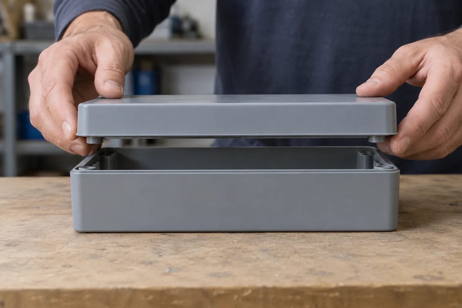
Resin-grade design data gives the review a material basis. Bring the proposed local sections, gate concept and cooling layout to the production molder. Flow and cooling analysis can help compare alternatives when thick pockets, flow access or shape stability remain uncertain. Representative molding trials can then show whether the selected geometry and process achieve the required appearance and fit.
A prototype that assembles well does not settle how a production mold will pack and cool the part. Review trial parts under comparable molding conditions and against the same cosmetic, dimensional and functional targets. If sink remains at a heavy junction, revisit that mass together with packing access and cooling. If the shell still distorts after the local section is improved, investigate the wider shrinkage and restraint pattern instead of extending the blend everywhere.
Once alternatives meet their acceptance targets, compare the complete delivery implications: molding cycle, any secondary work, assembly behavior, tool changes and maintenance needs. Keep a geometry revision that solves the relevant problem without adding an unacceptable burden elsewhere. Resin and tooling review must support that decision before production steel is committed.
Prepare a focused housing review
Bring the current CAD model with section views, the resin grade, the intended loads and the actual mating hardware. Add tolerances, texture and appearance requirements, plus photographs or observations from any molded samples. Include the proposed gate and cooling concept, available equipment and expected production volume when discussing the design with the molder.
With those inputs, the team can decide which unused bulk to remove, which supports to preserve and which alternatives need analysis or trial molding. Record where each candidate is expected to help and what observation would rule it out. That makes the next review a choice between workable housing designs rather than a search for a universal geometry ratio.
Frequently asked questions
Can a mold-flow result replace a molding trial?
Analysis helps compare proposed geometries and identify areas to investigate. Its conclusion depends on the material information and mold assumptions used. If an important cooling detail or process condition is unresolved, treat the result as guidance for the trial rather than proof of the finished surface or assembly fit.
Should more packing pressure be the first response to sink near a boss?
Discuss process adjustment with the molder after checking whether pressure can reach the affected region. A setting change may not compensate for a heavy junction or poor cooling access. Judge the trial against both appearance and dimensional behavior, since a surface improvement alone does not show that the housing remains acceptable.
How do I choose between a hollow boss and a separate mounting solution?
Start with the required fastening function and available space. A hollow boss may preserve a simple assembly if its remaining geometry carries the load. A separate support is worth evaluating when the integral feature forces excessive bulk, but it adds an interface whose fit, assembly effort and support behavior also need assessment.
What if the cosmetic side looks acceptable but the lid rocks?
Treat rocking as a fit problem even if no sink is visible. Check the mating surfaces, enclosure shape and attachment locations together. That evidence helps distinguish a local interference from a broader distortion pattern and directs the next geometry or molding review.