
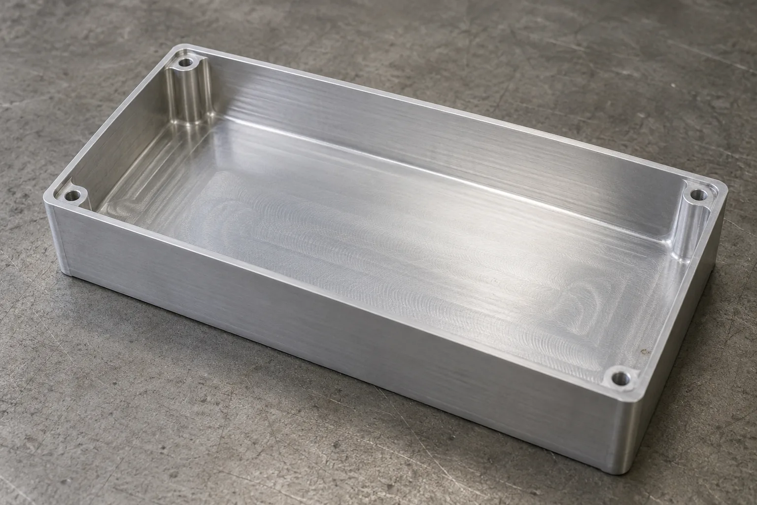
Why a lightweight housing can move during machining
Thin walls have less resistance to bending, so cutting or clamping forces can push them away from their intended position. In an aluminum enclosure with a large pocket, removing the interior leaves perimeter walls and internal partitions less supported than they were in the original stock.
A long stretch of wall can bend more readily than a shorter supported region. Corners, ribs and transitions change how neighboring material supports that stretch. Local thickness therefore matters together with span and surrounding geometry; a wall thickness considered workable elsewhere may behave differently in this housing.
During cutting, a flexible wall can move away from the tool and spring back afterward. That movement can leave uneven thickness or dimensional error. Chatter, a repeating vibration between the tool and part, may also mark the surface and make finishing less predictable. Heat can contribute additional movement.
Ask the machining supplier where support is lost as the pocket opens, and compare those locations with wall-thickness variation or chatter marks. A pattern concentrated along unsupported regions supports investigating stiffness and cutting engagement. Surface appearance alone does not establish the cause.
Why geometry can change after unclamping
An enclosure can look acceptable while held and move when released. The fixture may have bent it into position, so unclamping allows it to spring back. Another possible contributor is residual stress: internal stress already present in the stock that can redistribute as surrounding material is removed.
Large or uneven removal regions can disturb that balance. The remaining walls may move as material comes off, even without an excessive clamping load. Stock form and temper affect the starting condition, while the order of machining changes when the weak regions become exposed. Stress-relieved material may reduce a contributor without guaranteeing stable finished geometry. Alternative stock forms or stress-relieved material can affect purchasing cost and availability; assess their value through the resulting housing geometry in the agreed inspection state.
Distinguish these possibilities by recording shape before clamping, while held and after release using an agreed inspection method. Where practical, include observations after intermediate removal stages. A change associated with fixture tightening points toward workholding influence; movement that follows substantial removal also warrants a stock-and-sequence investigation.
Machining loads, fixture pressure and residual-stress movement can coexist. If the supplier reports several effects, test changes separately where feasible rather than attributing the final shape to the last operation. Keep the functional surfaces and evaluation conditions consistent so the observations remain comparable.
Choose geometry changes that protect the functional walls
For a wall that bends along an open stretch, shortening the unsupported span is a direct design option. A rib can provide support where its connection transfers load into a stiffer region. Local thickening or a suitable transition can also help, but the surrounding pocket and assembly need to accommodate the added material.
These remedies have different consequences. A rib occupies internal space; broader thickening adds mass over a larger region. Changing the pocket layout may preserve support while moving interference risk elsewhere. Review sealing, component clearance and assembly access before selecting a change.
If the geometry moves primarily as the stock is opened up, adding stiffness may improve handling without resolving the underlying movement. That condition calls for discussion of stock assumptions and balanced removal where feasible, alongside the design review. The choice remains conditional on the observed behavior.
| Observed condition or design need | Direction to evaluate | Tradeoff and evidence needed |
|---|---|---|
| A long wall flexes under machining loads | Shorten its free span or add a rib tied into a stiffer region | Check internal clearance and whether support reaches the affected wall. |
| A functional wall needs support but ribs obstruct the cavity | Retain material locally or revise the pocket transition | Compare added mass and usable space against the critical feature requirements. |
| Released shape changes as large regions are removed | Review stock condition and the removal pattern with the supplier | Establish whether a stock or sequence change improves the specified geometry; stiffness changes alone may be insufficient. |
| Only selected features control assembly or sealing | Concentrate tight requirements on those surfaces and dimensions | Verify that relaxed requirements elsewhere preserve fit and function. |
Give the fixture support without forcing the part into shape
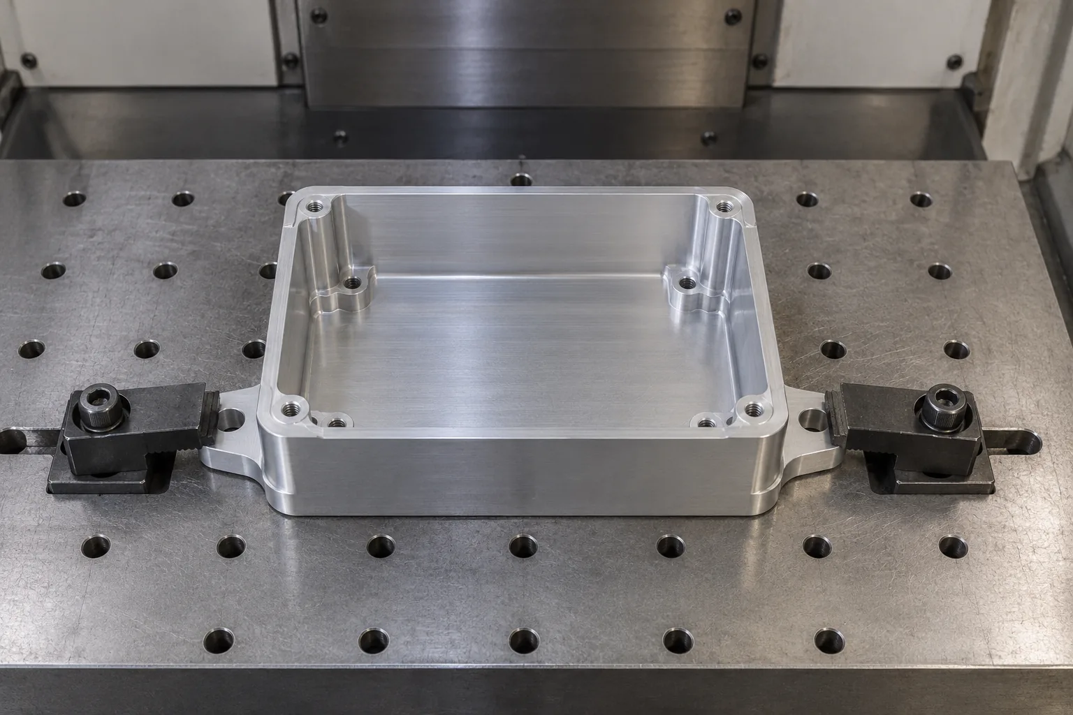
Provide datum and clamping regions that can carry fixture loads. A datum is a reference feature used to locate the part or define measurement. Stable reference regions help the supplier control position without pressing directly on a flexible wall.
Review the load path from each clamp into its support. Pressure on a wall with little backing can bend it before cutting begins. Retaining support during roughing, then changing the setup as the pocket opens, may be preferable to relying on the finished thin wall throughout the process. The workable approach depends on access and equipment.
Ask which cutting stages expose the least-supported areas and how cutter engagement will be managed there. Slower cutting, additional setups or intermediate inspection may be needed, with consequences for delivery cost. Finishing passes should be discussed together with support and stock remaining, rather than treated as an automatic cure.
If a trial still misses the functional requirement, use its observations to decide what to change. Fixture-induced movement calls for a different support or clamp arrangement; persistent wall deflection favors stronger geometry or adjusted cutting conditions. A repeatable removal-related shift may require a revised stock assumption or sequence.
Define the inspection state before comparing tolerances
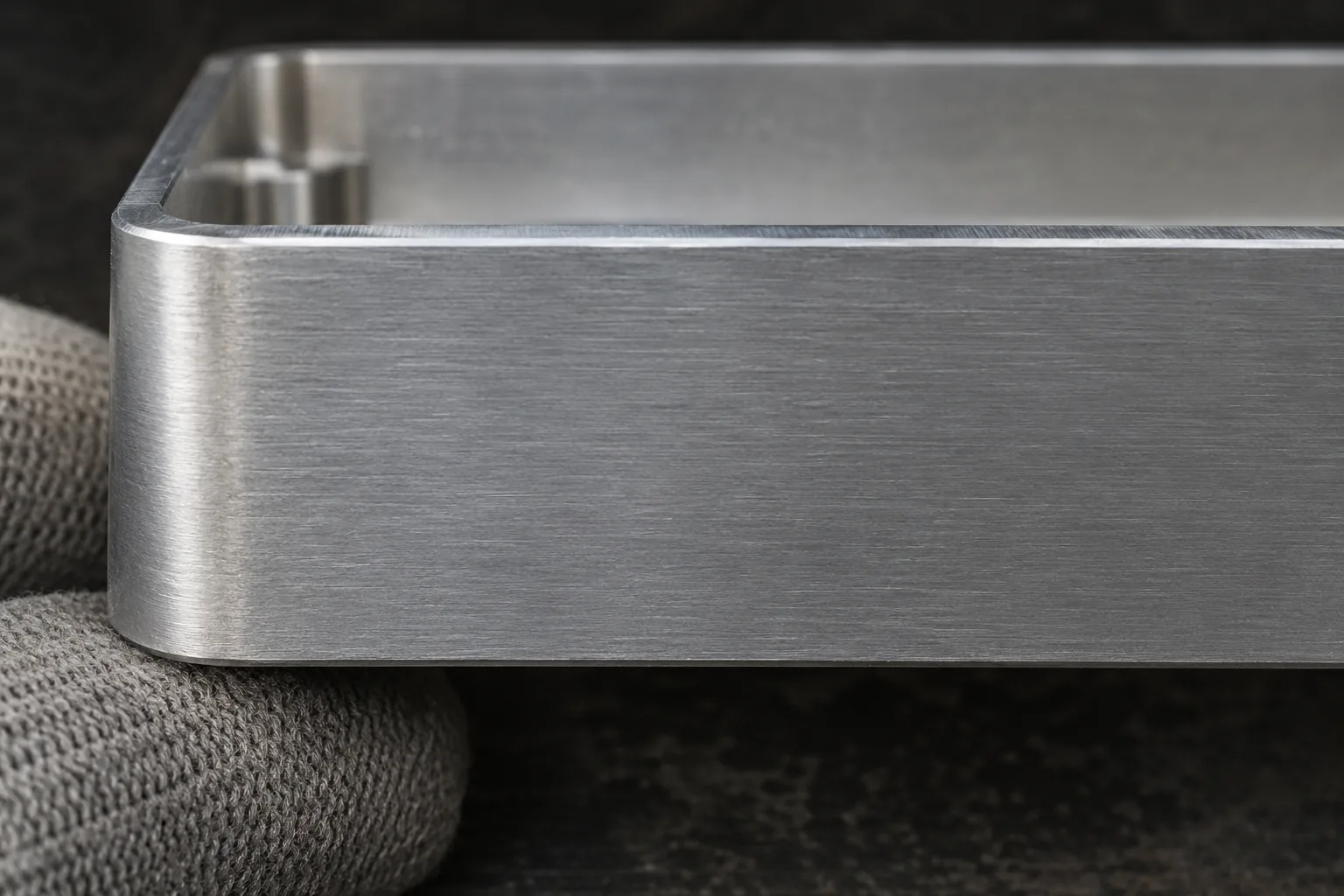
A measurement taken while the housing is restrained answers a different question from a measurement taken after release. The drawing and inspection agreement should state the condition relevant to function, including any assembly restraint that is genuinely part of use.
Wall thickness, flatness and positions of mating features can each be sensitive to movement, but they describe different risks. Identify which features govern sealing, fit or alignment. Compare measurements from the relevant state with those requirements, and account for finish and handling when planning the final evaluation.
Use consistent references and avoid measurement contact that noticeably deflects the wall. When held and released results disagree, retain both records with their conditions. Repeating the agreed assessment helps distinguish a measurement problem from repeatable part movement.
Use the housing's agreed functional state to decide whether its sealing and mating dimensions pass; observations in other states help trace fixture loading or material-removal effects. Compare machining and inspection costs only among routes that satisfy those requirements.
Bring the right evidence to the pre-prototype review
A useful prototype review connects the lightweighting objective with the features that must remain controllable. Give the supplier enough detail to explain where the part can be supported, what movement must be investigated and how the finished housing will be accepted.
- Mark walls and mating features whose shape affects sealing, alignment or assembly.
- Identify spans that remain unsupported as the main pocket and internal regions are machined.
- Provide the alloy, temper and proposed stock form, with material-condition evidence if available.
- Show reference surfaces, accessible clamping regions and areas that must remain free of fixture pressure.
- Separate function-critical tolerances from requirements that can be relaxed after an assembly review.
- Describe the finish, handling expectations and inspection condition that apply to the delivered part.
- Share the intended quantity and available process-capability evidence so prototype results can be assessed against production needs.
Turn the review into a design or process decision
Prepare the current drawing and model, material specification, functional acceptance criteria and any observations showing when movement appears. Bring held-versus-released measurement records or sample photos if they exist, along with cavity-clearance and mass constraints.
With these inputs, the machining supplier can propose a bounded trial and identify whether local reinforcement, a different support arrangement or a stock-and-sequence change deserves priority. Use the trial to choose a route that meets the required geometry with acceptable mass, space and delivery effort. Achievable tolerances remain specific to the part and process.
Frequently asked questions
Why can a prototype look satisfactory while production parts become troublesome?
A prototype result applies to its material condition, setup and handling. Changes in stock or process between runs can expose movement that the initial sample did not reveal. Ask whether the successful conditions can be maintained across the intended quantity before treating the prototype as capability evidence.
Does a quieter finishing cut mean the housing is dimensionally stable?
Reduced chatter can improve the surface while released geometry still drifts. Include the finished part's functional measurements in the agreed state; an improved appearance addresses only part of the risk.
Can an enclosure be accepted under assembly restraint instead of in its free state?
Yes, if that restraint is part of actual service and the drawing and inspection agreement specify the constrained condition and required fit or sealing function. A temporary fixture that makes a mismatched housing appear correct does not establish acceptable assembly performance.
When is a drawing review enough, and when is a machining trial warranted?
A review can resolve unclear requirements or inaccessible support regions. A trial is valuable when the intended geometry, stock and tolerance combination lacks relevant capability evidence, especially when observations could change the design choice.