
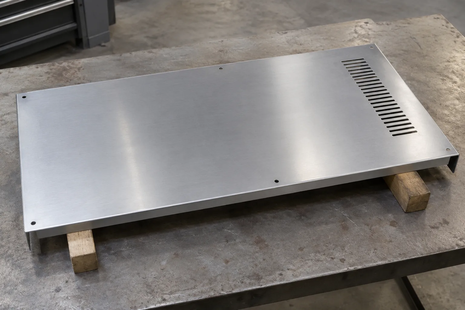
Why a formed panel changes shape
A broad enclosure face can flex under handling or fastening loads. Residual stresses from sheet production and cutting may redistribute as openings are cut.
Bending stretches the outside and compresses the inside. Elastic recovery after tool release opens the bend: this is springback. Material grade and temper affect the response to strain; rolling direction can affect bending behavior. Compensation must therefore suit the actual sheet. Small flange-angle differences shift mounting edges, with long spans and asymmetric openings amplifying alignment problems.
Bends and openings need room to work
An opening within the bending region can stretch; a narrow adjacent strip offers less resistance to movement. Unequal flanges and corner reliefs can concentrate deformation.
Changing thickness or radius changes the strained region and may require different tooling and springback compensation. Recheck nearby openings and flange positions together. Compare slots and mounting edges before and after forming; movement may justify relocating features, revising reliefs, or cutting after forming where accessible. Agree practical geometry with the fabricator rather than applying a universal ratio.
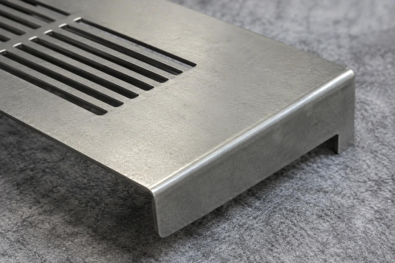
Choose stiffness changes by the observed problem
Thicker sheet resists flexing but adds weight and changes forming demands; reassess bends and nearby features alongside stiffness. Ribs, beads, hems, or shorter unsupported spans may be more economical if space and appearance permit.
| Observed condition | Design direction | Tradeoff to check |
|---|---|---|
| Face flexes between supports | Add support or a stiffness feature; evaluate thickness if geometry is constrained | Interior clearance, visible marks, weight, tooling |
| Flange angle or nearby opening shifts after bending | Revise bend compensation, feature location, relief, or forming sequence | Tool access and added operations |
| Panel fits freely but moves when fastened | Check frame geometry and mounting constraints; consider intentional adjustment | Sealing, alignment, and load transfer |
Include downstream operations in the dimensional plan
Already formed flanges change later positioning, support, and tool access. Under consistent measurement support, record flange angles and mounting-edge positions after each bend. A shift introduced at one bend or appearing after subsequent clamping warrants reviewing sequence or support with the fabricator; no sequence works universally.
Weld heating and cooling can pull edges; insert installation can deform unsupported sheet. Coating or plating builds up interfaces, and powder-coat curing introduces process-specific heat exposure. Check holes, seams, masking, and frame fit after finishing. Extra setups, correction, custom tooling, cosmetic demands, and finish coordination can increase cost and lead time.

Specify fit without hiding free-state variation
Compare free-state shape with frame geometry, then record gaps during intended fastening. Define datums—measurement references—from functional interfaces, and distinguish surface flatness from profile relative to those references.
If function depends only on mounting edges, sealing zones, or hole fit, define those zones and assembly restraints before tightening whole-face free-state flatness. If appearance or sealing requires overall shape control, retain that requirement with specified inspection support. Undefined restraints make measurements difficult to compare; unnecessarily tight overall limits add correction and inspection work. State acceptance before or after finish. Forced assembly must not conceal nonconforming parts; sample success or machine specifications alone do not establish production capability.
Prepare an RFQ that supports a design decision
Bring the following inputs to the fabricator. They enable a decision between geometry changes, additional support, thickness changes, and process development.
- Native CAD, controlled drawing, and flat-pattern intent if available.
- Material grade, condition, thickness, and quantity.
- Bend radii, directions, cutouts, reliefs, inserts, and weld details.
- Mating-frame geometry, datums, and functional fit zones.
- Finish, masking, cosmetic requirements, and packaging needs.
- Inspection conditions, stage-by-stage observations, and target lead time.
Frequently asked questions
Why can a prototype fit while later panels do not?
Material lots, tooling setups, and forming or finishing conditions may differ. Compare those inputs and the measurement restraints before attributing variation to the design.
Can straightening alone solve the problem?
It may correct an individual panel, but adds handling and can affect the visible finish. Establish why movement occurs and whether the correction remains stable through downstream operations.
When should adjustable mounting holes be considered?
When controlled assembly adjustment can absorb interface variation without compromising sealing, alignment, or load transfer. They will not correct a bowed cosmetic face.