
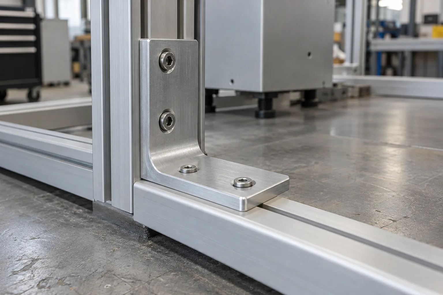
Strength resists damage; stiffness limits movement
For 6061 vs 7075 aluminum for CNC machining, start with what limits the bracket. A part can bend too far without permanently deforming. Strength describes resistance to yielding or failure; stiffness describes how much it moves under load. Hardness concerns local indentation and does not establish an assembly load rating.
7075 can offer higher strength in suitable tempers, while the elastic stiffness of these alloys is broadly similar. If alignment is lost through elastic bending, review bracket depth, span and support before changing material. If permanent deformation limits an otherwise constrained design, evaluate certified 7075 properties against the actual loading.
Follow the load through the bracket and its fasteners
A narrow section beside a hole, a sharp inside corner or insufficient thread engagement can govern failure before the wider body does. Section depth and a shorter unsupported reach can reduce bending; their benefit depends on available space and how the bracket is attached.
Map the force from the supported component into each mounting surface. Examine hole bearing, thread pullout and corner stresses as well as the body. Where repeated loads or impact are credible, assess those conditions separately. If a local feature governs, revise its geometry or fastening arrangement and repeat the analysis before treating an alloy upgrade as the remedy.
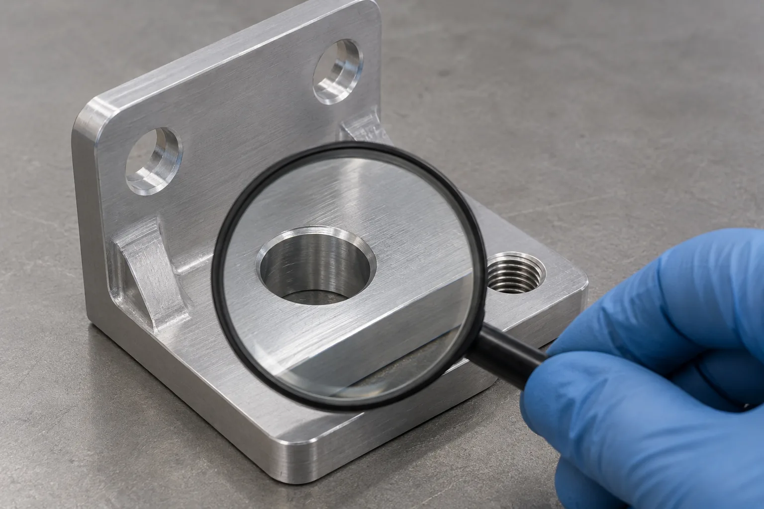
Let exposure and finishing change the shortlist
6061 is generally a more practical starting point when corrosion resistance carries substantial weight. A strength-driven 7075 choice needs closer review of temper, exposure and protection: stress-corrosion cracking is cracking promoted by sustained stress in a susceptible material and environment.
Both grades can be anodized, but alloy and process can affect appearance and finished dimensions. Ask the processor how the intended treatment affects mating faces, holes and threads. Specify masking or conductive contact areas where required. For a finish-sensitive assembly, inspect representative finished samples rather than assuming the alloy name guarantees color, fit or protection.
Evaluate the machining route and the complete quotation
Both alloys are CNC-machinable. Cutting behavior depends on material condition, tooling and the part design; higher strength alone does not mean poorer machinability. Thin walls and uneven material removal can expose residual stresses or allow the part to move during machining.
Request a stock-form and temper proposal with certification and property orientation relevant to the stressed features. Have the supplier explain workholding, machining sequence and inspection after release from the fixture and after finishing. Compare quotes at the required quantity, including stock availability, material removal, finish processing, inspection, rework exposure and maintenance needs. Price and delivery remain project-specific.
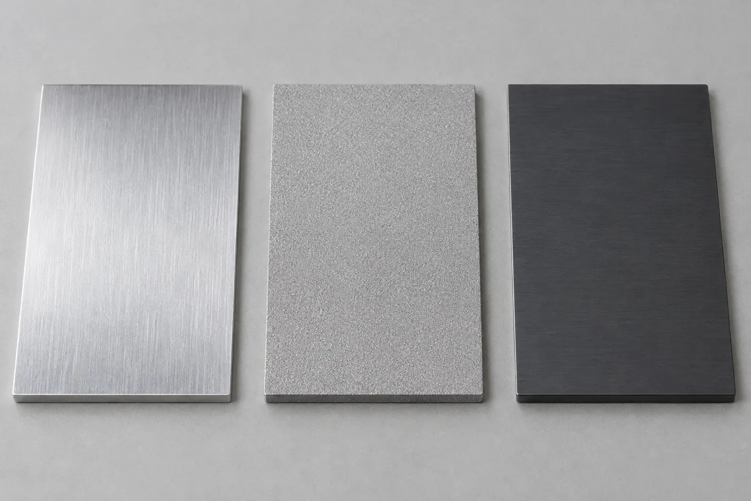
Choose a route, then test the assumption that drives it
Evaluate the candidates for the same intended use, loading, environment and acceptance criteria. The limiting requirement determines the branch:
| Limiting condition | Preferred direction | Evidence that could change it |
|---|---|---|
| Adequate load margin; protection or finish dominates | Start with 6061 and the specified finish. | Reject the route if certified properties or representative exposure and fit checks cannot meet the requirement. |
| Strength shortfall with little room to enlarge the bracket | Evaluate 7075 with an appropriate temper. | Reconsider if corrosion risk, fatigue assessment or the protective treatment undermines the required service behavior. |
| Excessive elastic movement or a weak joint detail | Revise section shape, support or fastening first. | Retain an alloy change only if the revised design still needs additional strength. |
Prepare an RFQ that supports an engineering decision
If the proposed route falls short, adjust the governing feature or protection strategy and reassess; consider a material alternative when neither candidate meets the application. Once viable routes meet the same criteria, compare the complete delivered condition, including verification, post-processing and upkeep.
Provide the following so the supplier can assess feasibility, identify unresolved risks and return a comparable proposal:
- 3D CAD model and controlled 2D drawing, including assembly interfaces.
- Alloy and temper requirement, or explicit permission to propose an alternative.
- Load directions, application description, repeated-load or impact exposure and service environment.
- Critical dimensions, tolerances, thread details and inspection acceptance requirements.
- Finish, color expectations, masked surfaces and electrically conductive areas.
- Quantity, certification documents, assembly needs and target delivery date.
Frequently asked questions
Can an existing bracket be replaced with the other alloy without redesign?
Treat substitution as a design change. Check the original approval basis, fastening behavior, environmental protection and finished fit. Similar appearance does not establish interchangeability; a substitution needs evidence for the actual assembly.
Does a material certificate prove that the machined bracket is safe?
It documents the supplied material against its stated specification. It does not validate the load path, machining condition or service performance. Use it alongside design assessment and the inspection or testing appropriate to the identified failure risks.
What should a prototype trial establish when fatigue is a concern?
A short static trial can establish fit and immediate deformation behavior, but cannot establish repeated-load durability. Define a representative load history and examine likely crack-starting features; use an engineering fatigue assessment to decide what further validation is needed.